Heat pipe operating fluid, heat pipe, and method for manufacturing the heat pipe

Inactive Publication Date: 2005-05-05
HON HAI PRECISION IND CO LTD
View PDF10 Cites 61 Cited by
  • Summary
  • Abstract
  • Description
  • Claims
  • Application Information

AI Technical Summary

Benefits of technology

[0010] Accordingly, an object of the present invention is to

Problems solved by technology

If the carbon fibers are large, the capillary performance of the wick 12 is likely to be poor.
Any heat pipe adopting carbon fibers should not employ large fibers, otherwise poor thermal conductivity is like

Method used


Image

  • Heat pipe operating fluid, heat pipe, and method for manufacturing the heat pipe
  • Heat pipe operating fluid, heat pipe, and method for manufacturing the heat pipe
  • Heat pipe operating fluid, heat pipe, and method for manufacturing the heat pipe

Examples


Embodiment Construction

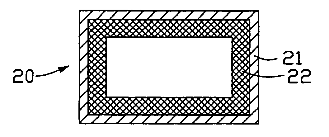
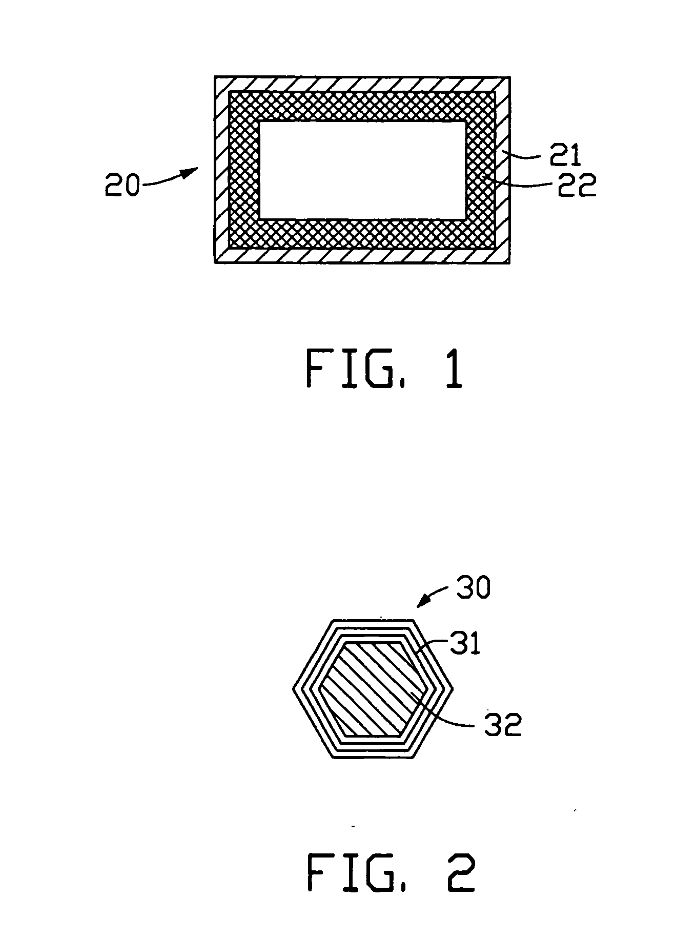
[0026] Referring to FIG. 1, a heat pipe 20 of the present invention comprises a pipe 21, a wick 22, and an operating fluid (not labeled). The wick 22 is a capillary structure comprising a carbon nanotube layer, and is fixed to an inside wall of the pipe 21. The operating fluid is sealed in the pipe 21 and soaks into the wick 22.

[0027] The pipe 21 is a metal tube. A material of the pipe 21 can be selected from the group consisting of copper, aluminum, steel, carbonic steel, stainless steel, iron, nickel, titanium, and any alloy thereof. A cross-section of the pipe 21 is circular, elliptical, square, triangular or rectangular. A width of the pipe 21 is in the range from 2 to 200 micrometers, and a length of the pipe 21 is in the range from several micrometers (μm) to several tens of meters (m). In the preferred embodiment of the present invention, the pipe 21 is a copper tube having a length of 80 micrometers. The cross-section of the pipe 21 is rectangular, and the cross-section has...


PUM


Abstract

A heat pipe (20) includes a pipe (21), a wick (22), and an operating fluid. The wick is a capillary structure including a carbon nanotube layer, and is fixed to an inside wall of the pipe. The operating fluid is sealed in the pipe and soaks into the wick. The operating fluid includes a pure liquid, and a plurality of nanometer-scale particles uniformly suspended in the pure liquid. The nanometer-scale particles can be carbon nanocapsules (30) or particles of a metal (32) with high thermal conductivity. Each carbon nanocapsule can further have a metal with high thermal conductivity filled therein. The carbon nanotube layer contains carbon nanotubes of small size and high thermal conductivity, therefore the capillary performance of the wick is good. Further, because the operating fluid includes nanometer-scale particles with high thermal conductivity, this ensures that the operating fluid has high thermal conductivity.

Description

BACKGROUND OF THE INVENTION [0001] 1. Field of the Invention [0002] The invention relates generally to thermal transmitting structures, and more particularly to a heat pipe having an operating fluid and a method for manufacturing the heat pipe. [0003] 2. Description of the Prior Art [0004] Electronic components such as semiconductor chips are becoming progressively smaller, while at the same time heat dissipation requirements thereof are increasing. In many contemporary applications, a heat pipe is one of the most efficient systems in use for transmitting heat away from such components. [0005] Referring to FIG. 4, a typical heat pipe 10 is a vessel that comprises a pipe 11, a wick 12, and a precise amount of liquid operating fluid 13. The wick 12 is a capillary structure, and is fixed to an inside wall (not labeled) of the pipe 11. The liquid operating fluid 13 is sealed in the pipe 11 and soaks the wick 12. One end of the heat pipe 10 is an evaporator section, and the other end of ...

Claims


Application Information

Patent Timeline
IPC IPC(8): C09K5/10F28D15/02F28D15/04
CPCB82Y30/00F28D15/046F28D15/0233C09K5/10
Inventor LIN, JHY-CHAINCHEN, GA-LANE
Owner HON HAI PRECISION IND CO LTD
Why Eureka
Try Eureka