
Methods and apparatus for polishing a substrate

a technology of substrate and polishing method, which is applied in the direction of electrolysis components, manufacturing tools, lapping machines, etc., can solve the problems of removing copper material from features by anodic dissolution, leaving behind barrier material residue on the substrate surface, and conventional ecmp processes that have less than satisfactory barrier removal ra

Inactive Publication Date: 2005-05-05
APPLIED MATERIALS INC
View PDF99 Cites 51 Cited by
  • Summary
  • Abstract
  • Description
  • Claims
  • Application Information

AI Technical Summary

Problems solved by technology

However, as the limits of circuit technology are pushed, the shrinking dimensions of interconnects in VLSI and ULSI technology have placed additional demands on processing capabilities.
Conventional ECMP processes have been observed to have less than satisfactory barrier removal rates and often leave behind barrier material residue on a substrate surface.
Conductive barrier material residues may provide conductive paths between otherwise isolated copper features, referred to as residual conductivity, and if in contact with a power source, detrimentally result in excess removal of copper material from features by anodic dissolution.
Extending polishing processes to remove barrier residues has also been observed to result in excess removal of copper from features.
Excess copper removal from features may result in the formation of topographical defects, such as concavities or depressions, referred to as dishing.
Dishing results in a non-planar surface that detrimentally affect subsequent substrate processing, such as impairing the ability to print high recomposition lines during subsequent photolithographic steps, and further detrimentally affects subsequent surface topography of the substrate and device formation.
Dishing has also bee observed to detrimentally affect the performance of devices by lowering the conductance and increasing the resistance of the devices, contrary to the benefit of using higher conductive materials, such as copper.

Method used


Image

  • Methods and apparatus for polishing a substrate
  • Methods and apparatus for polishing a substrate
  • Methods and apparatus for polishing a substrate

Examples


embodiment

An Apparatus Embodiment

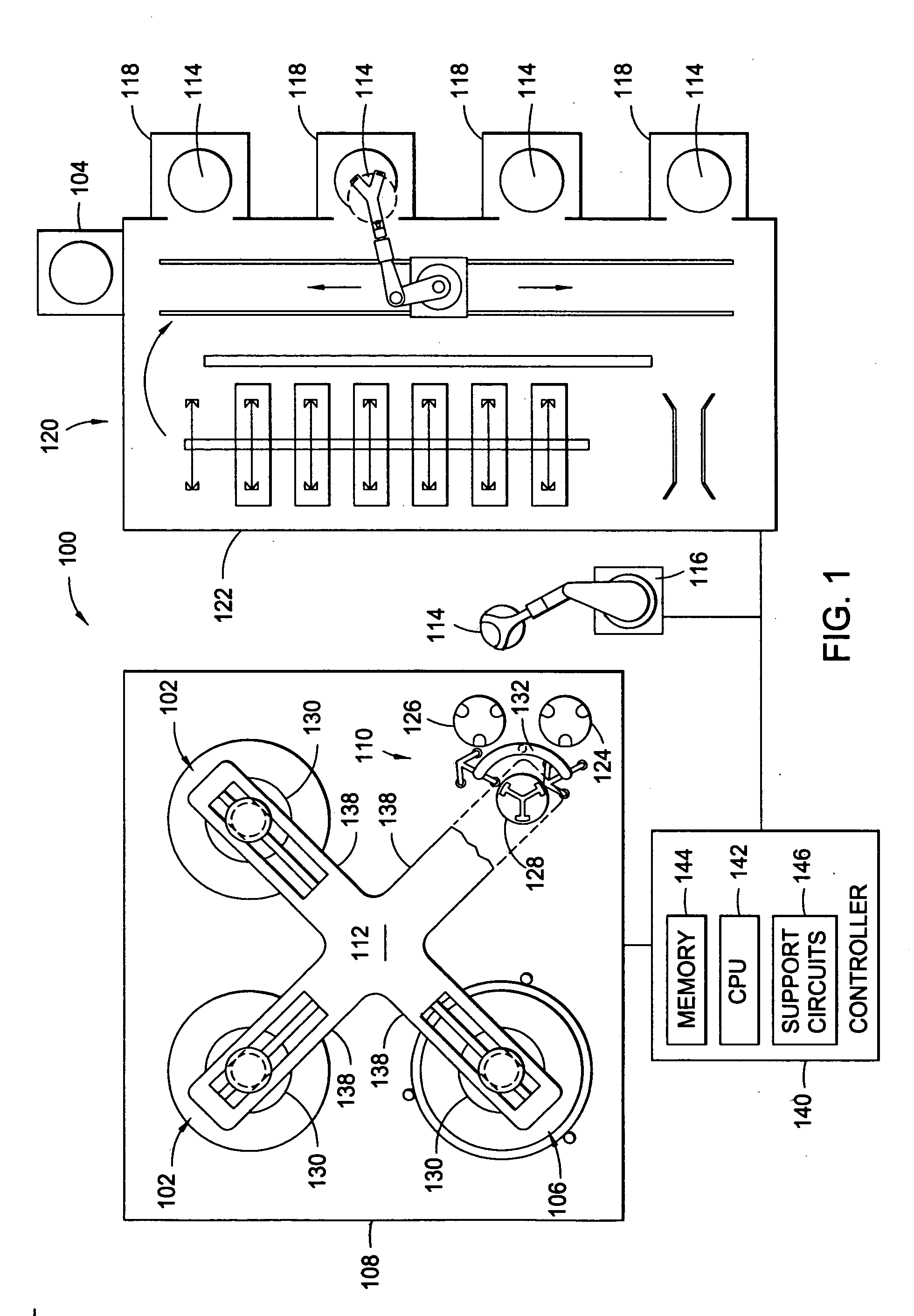
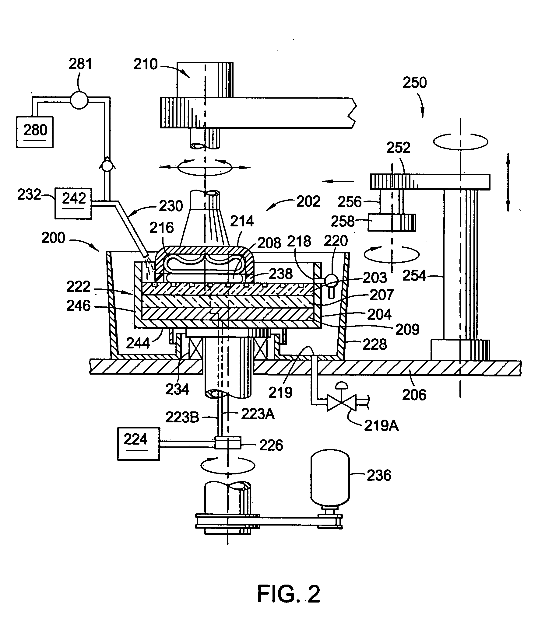
[0023]FIG. 1 depicts one embodiment of an electrochemical processing apparatus suitable for performing the processes described herein. The electrochemical processing apparatus 100 has at least one electrochemical mechanical polishing (ECMP) station 102, and optionally, the system 100 may include at least one conventional polishing station 106 disposed adjacent the ECMP station 102 on a single platform or tool. One polishing tool that may be adapted to benefit from the invention is a REFLEXION® chemical mechanical polisher available from Applied Materials, Inc. located in Santa Clara, Calif. Examples of other polishing tools that may be adapted to benefit from the invention are the MIRRA® chemical mechanical polisher and the MIRRA MESA™ chemical mechanical polishers also available from Applied Materials, Inc.

[0024] The exemplary apparatus 100 generally includes a base 108 that supports the one or more ECMP stations 102, the one or more polishing stations 106, ...


PUM

PropertyMeasurementUnit
Pressureaaaaaaaaaa
Pressureaaaaaaaaaa
Pressureaaaaaaaaaa

Abstract

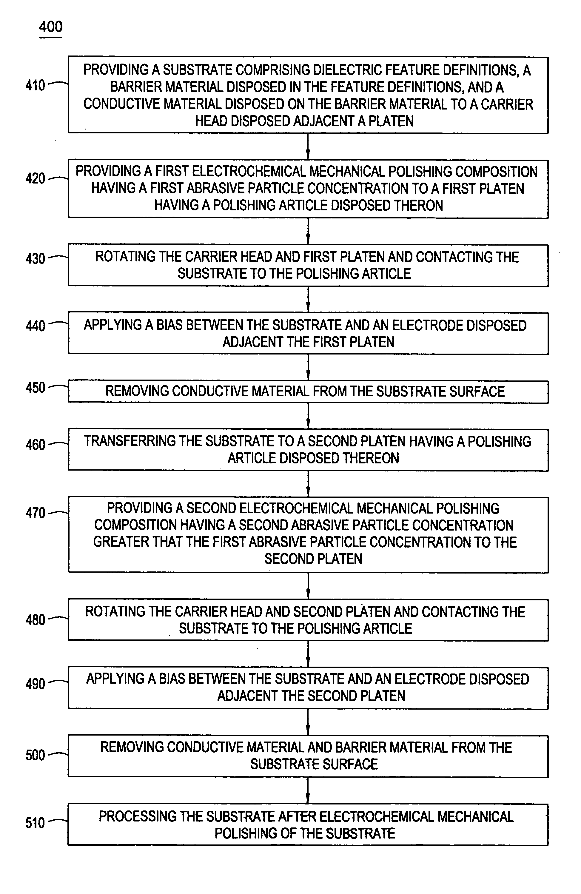
Polishing compositions and methods for removing conductive material and barrier layer materials from a substrate surface are provided. Generally, variable amounts of abrasive particles are used for removing conductive material and barrier layer materials. In one aspect, a process is provided including providing an polishing composition between the first electrode and the substrate, wherein the polishing composition comprises a first concentration of abrasive particles, applying a bias between the first electrode and the second electrode, providing relative motion between the substrate and the polishing article, removing conductive layer material from the substrate, introducing abrasive particles to the polishing composition to form a second concentration of abrasive particles greater than a first concentration of abrasive particles, and removing barrier layer material from the substrate. The abrasive particles may be incrementally introduced or pulsed during a polishing process.

Description

CROSS-REFERENCE TO RELATED APPLICATIONS [0001] This application claims benefit of U.S. provisional patent application Ser. No. 60 / 507,611, filed Oct. 1, 2003, which is herein incorporated by reference.BACKGROUND OF THE INVENTION [0002] 1. Field of the Invention [0003] Embodiments of the present invention relate to compositions and methods for removing conductive materials from a substrate. [0004] 2. Background of the Related Art [0005] Reliably producing sub-half micron and smaller features is one of the key technologies for the next generation of very large scale integration (VLSI) and ultra large-scale integration (ULSI) of semiconductor devices. However, as the limits of circuit technology are pushed, the shrinking dimensions of interconnects in VLSI and ULSI technology have placed additional demands on processing capabilities. Reliable formation of interconnects is important to VLSI and ULSI success and to the continued effort to increase circuit density and quality of individua...

Claims


Application Information

Patent Timeline
IPC IPC(8): B23H5/08B24B37/04B24B57/02C25F3/02H01L21/321
CPCB23H5/08B24B37/042H01L21/32125B24B57/02C25F3/02B24B37/345
Inventor MAVLIEV, RASHID A.DUBOUST, ALAINTSAI, STAN D.
Owner APPLIED MATERIALS INC
Learn More