

Substrate holding technique
a holding technique and substrate technology, applied in the field of substrate holding technique, can solve the problems of complex structure of the electricity supply system for mounting and demounting the mask to and from the mask chuck, and the mask holding precision is degraded, so as to achieve high surface precision
- Summary
- Abstract
- Description
- Claims
- Application Information
AI Technical Summary
Benefits of technology
Problems solved by technology
Method used
Image

Examples
embodiment 1
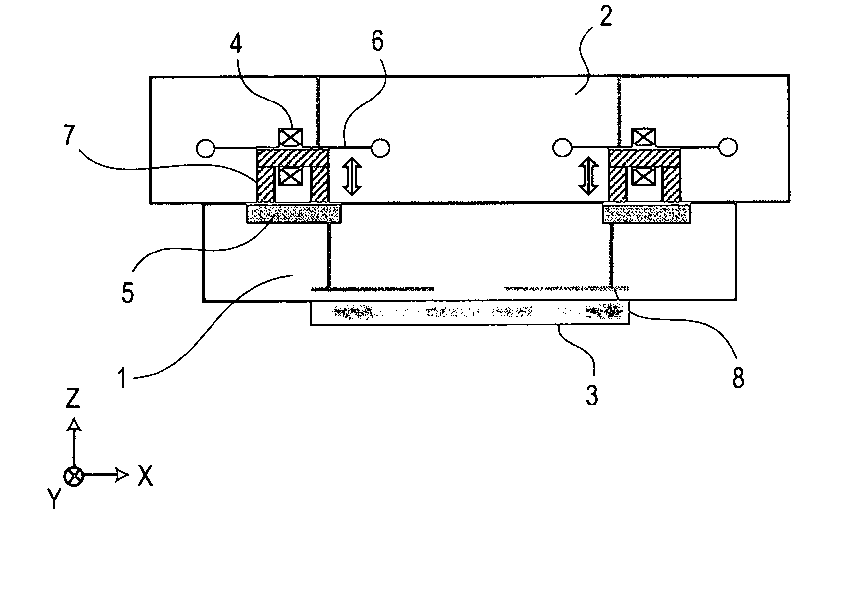
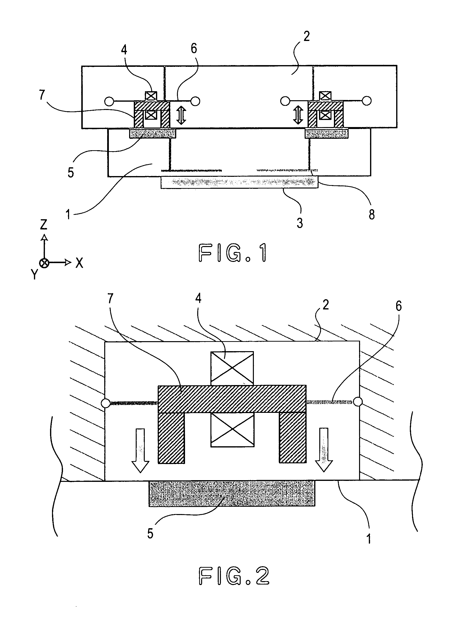
[0028] A first embodiment of the present invention will be described with reference to FIGS. 1 and 2. FIGS. 1 and 2 illustrate, in enlarged magnification, a mask stage and a mask chuck portion, disposed above a projection optical system of an exposure apparatus such as shown in FIG. 8. In FIG. 1, denoted at 1 is a mask chuck (substrate holding member), and denoted at 2 is a mask stage (stage) movable in a predetermined direction. The mask chuck has targets formed thereon, for measurement of position, angle and focus of the mask stage 2. The scan direction of the mask stage 2 is in Y-axis direction in FIG. 1. The mask chuck 1 having a mask (substrate) 3 held thereon is mounted to the mask stage 2. The mask chuck 1 and the mask stage 2 are provided with attracting means for mountably and demountably supporting the mask chuck 1 on the mask stage 2. The attracting means comprises a coil ion core 7 (second member) provided at the mask stage 2 side and a ferromagnetic material member (fir...
embodiment 2
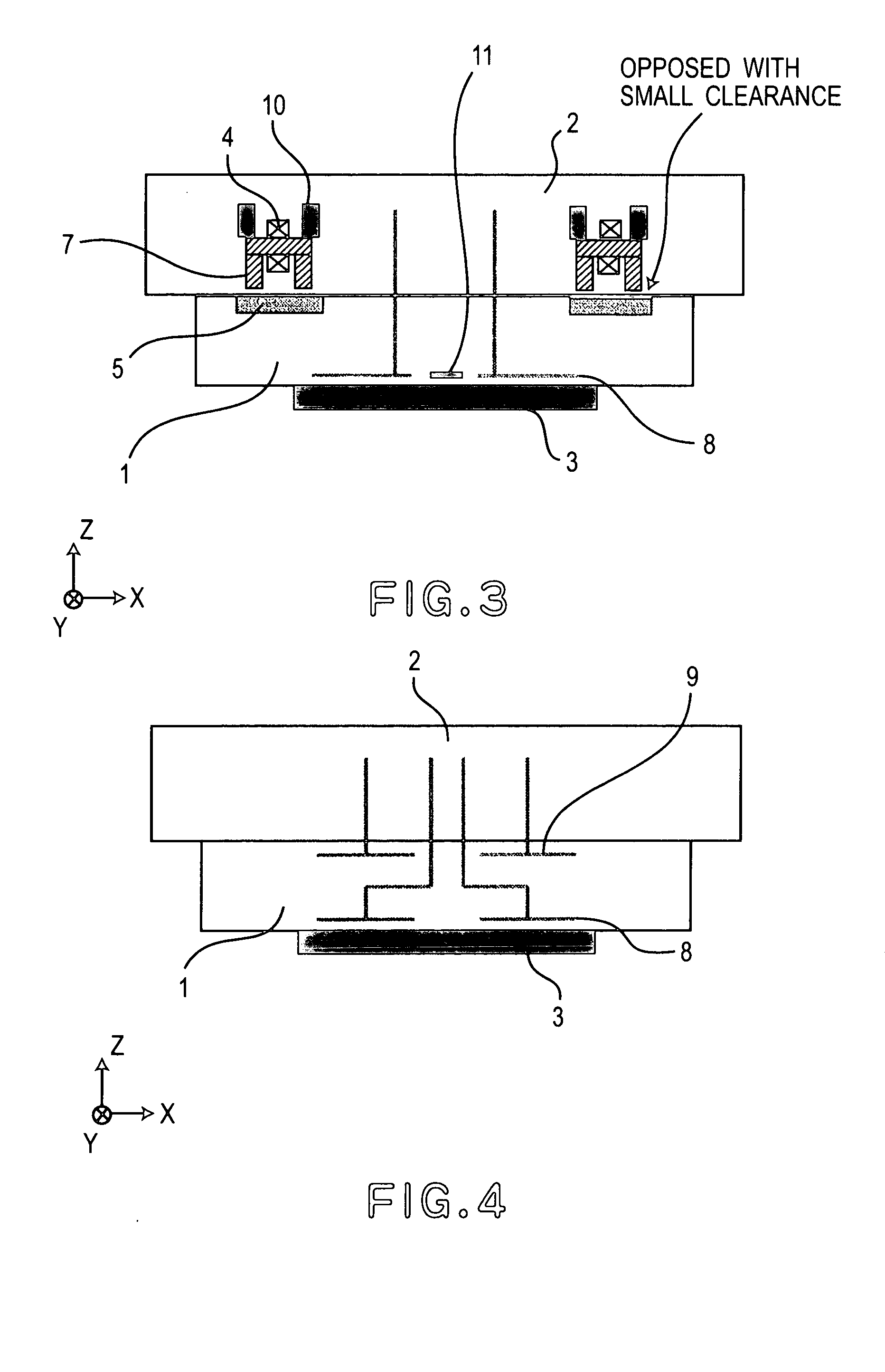
[0034] A second embodiment of the present invention will be described with reference to FIG. 3. In FIG. 3, like reference numerals are assigned to components corresponding to those of the FIG. 1 embodiment, and description therefor will be omitted. Only distinctive features will be explained.
[0035] In the second embodiment, the second member at the mask stage 2 side (i.e., coil iron core 7) and the first member at the mask chuck 1 side (i.e., ferromagnetic material member 5) are disposed close to each other with a clearance, like the structure shown in FIG. 2. By disposing the coil iron core 7 and the ferromagnetic material member 5 opposed to each other with a clearance as described above, unwanted deformation of the mask chuck 1 due to their mutual surface precision can be avoided. Furthermore, each coil iron core 7 is provided with a piezoelectric actuator 10 or, alternatively, a distance adjusting mechanism (not shown), such that the flatness of the mask chuck 1 can be correcte...
embodiment 3
[0037] A third embodiment of the present invention will be described with reference to FIG. 4. In FIG. 4, like reference numerals are assigned to components corresponding to those of the embodiments of FIGS. 1-3, and description therefor will be omitted. Only distinctive features will be explained.
[0038] In the third embodiment, in order that a mask chuck 1 is held on a mask stage 3 by electrostatic attraction force, mask-chuck electrostatic chuck electrodes (electrostatic attracting means) 9 are provided above the mask chuck 1. Each electrostatic chuck electrode 8 is connected to an electricity supplying unit (not shown) through an electricity supplying path such as wire or metal plate, for example. In this example, a connecting member such as a brush, for example, is used at the connection of electricity supplying path, between the mask chuck 1 and the mask stage 2. With this structure, when the mask chuck 1 is mounted to the mask stage 2, from an electricity supplying unit (not ...
PUM
| Property | Measurement | Unit |
|---|---|---|
| wavelength | aaaaa | aaaaa |
| movement | aaaaa | aaaaa |
| magnetic field | aaaaa | aaaaa |
Abstract
Description
Claims
Application Information