Centrifugal fan
- Summary
- Abstract
- Description
- Claims
- Application Information
AI Technical Summary
Benefits of technology
Problems solved by technology
Method used
Image

Examples
first embodiment
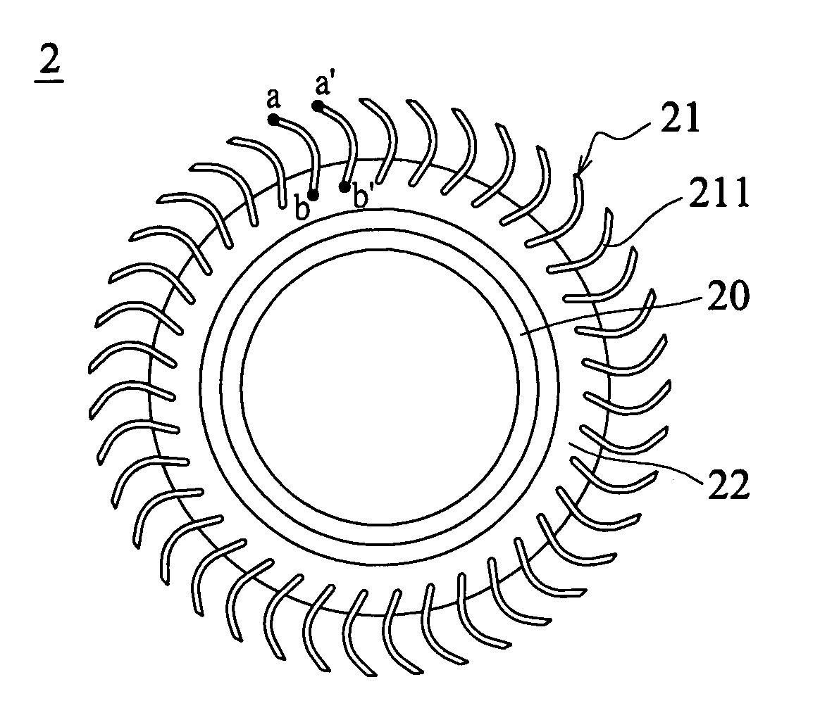
[0030] Referring to FIG. 2, a centrifugal fan 2 according to the invention includes a hub 20 and an impeller 21. The hub 20 is for securing the centrifugal fan 2 to a rotation shaft, which rotates to drive the fan. The impeller 21 is composed of a plurality of blades 211, each of which has a paraxial side and a non-paraxial side. The paraxial sides of the blades 211 are mounted around the outer circumference of the hub 20. The paraxial sides of the blades 211 are formed to have the backward leaning structures, and the non-paraxial sides of the blades 211 are formed to have the forward leaning structures. As shown in FIG. 2, each blade 211 of the impeller 21 in the top view has a spoon-like shape. According to this structure, an interval aa′ between the non-paraxial ends of the blades 211 is made relatively smaller than an interval bb′ between the paraxial ends of the blades 211.
second embodiment
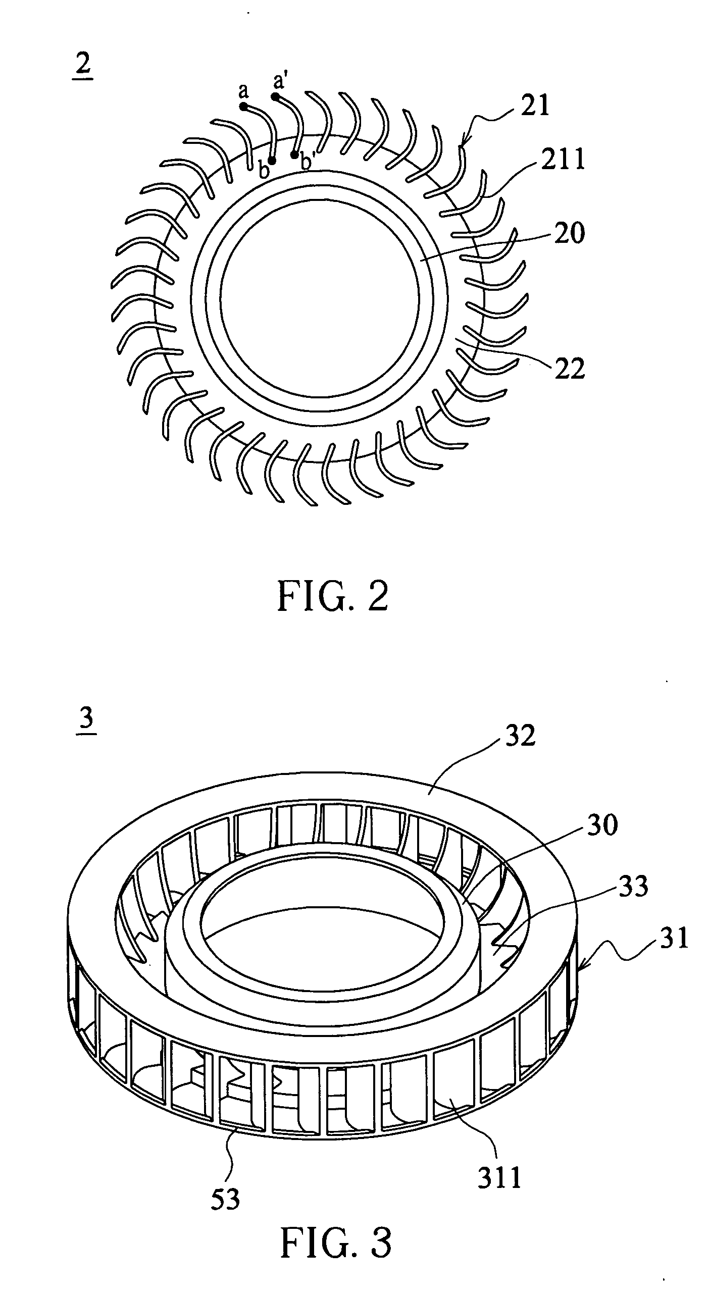
[0031] Referring to FIG. 3, a centrifugal fan 3 according to the invention includes a hub 30, an impeller 31 and an anti-decompression cap 32. The hub 30 is for securing the centrifugal fan 3 to a rotation shaft, which rotates to drive the fan. The impeller 31 is composed of a plurality of blades 311, each of which has a paraxial side and a non-paraxial side. The paraxial sides of the blades 311 are mounted around the outer circumference of the hub 30. The anti-decompression cap 32 has a ring-shaped structure connected to an inlet side of the impeller 31. The inner diameter of the anti-decompression cap 32 may be greater than, equal to or smaller than the diameter of the inlet of the impeller 31. The dimension of the inlet equals the region formed by the lines for connecting the paraxial ends of the blades 311 at the inlet side. The outer diameter of the anti-decompression cap 32 is greater than, equal to, or smaller than the outer diameter of the impeller 31. For example, the outer...
third embodiment
[0032] Referring to FIG. 4a, a centrifugal fan 4 according to the invention includes a hub 40 and an impeller 41. The hub 40 is for securing the centrifugal fan 4 to a rotation shaft, which rotates to drive the fan. The impeller 41 is composed of a plurality of blades 411, each of which has a paraxial side and a non-paraxial side. The paraxial sides of the blades are mounted around the outer circumference of the hub 40. The radial width cc′ at the inlet side of the blade 411 is relatively smaller than the radial width dd′ at the lee side such that the blade 411 forms a chamfer structure at the paraxial side. The lee side is opposite to the inlet side. The chamfer structure may be an arced chamfer, curved chamfer (as shown in FIG. 4b) or a linear chamfer (as shown in FIG. 4c). Also, the axial height ed′ at the paraxial side of the blade 411 may be adjusted so that the working area of the blades may be properly enlarged or reduced. The axial height ed′ at the paraxial side of the blad...
PUM
 Abstract
Description
Claims
Application Information
 - Generate Ideas
- Intellectual Property
- Life Sciences
- Materials
- Tech Scout
- Unparalleled Data Quality
- Higher Quality Content
- 60% Fewer Hallucinations
Browse by: Latest US Patents, China's latest patents, Technical Efficacy Thesaurus, Application Domain, Technology Topic, Popular Technical Reports.
© 2025 PatSnap. All rights reserved.Legal|Privacy policy|Modern Slavery Act Transparency Statement|Sitemap|About US| Contact US: help@patsnap.com