
Bone densitometer providing improved longitudinal studies

a bone densitometer and longitudinal study technology, applied in the field of xray bone densitometers, can solve the problems of hampered detailed comparison of bone subregions

Inactive Publication Date: 2005-05-05
GENERAL ELECTRIC CO
View PDF23 Cites 6 Cited by
  • Summary
  • Abstract
  • Description
  • Claims
  • Application Information

AI Technical Summary

Benefits of technology

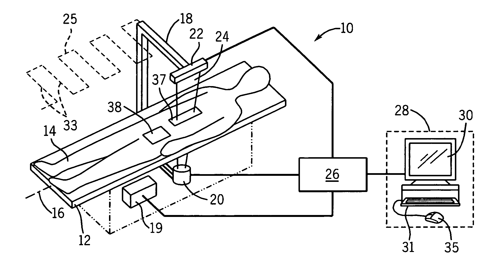
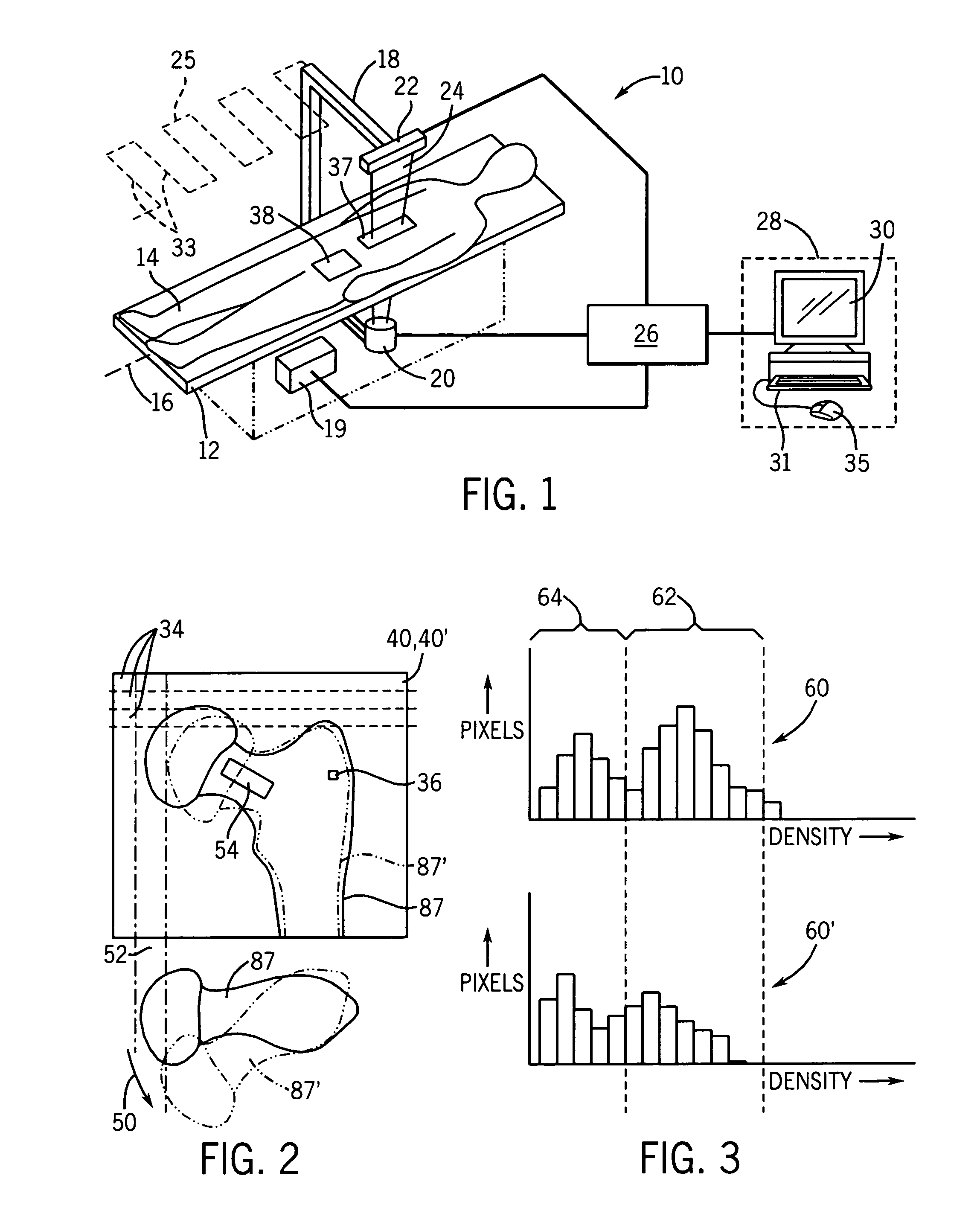
[0008] The present invention provides a computer-assisted bone densitometer in which software assesses changes in positioning of a patient between image acquisitions, alerting the operator to reposition the patient and / or correcting the acquired images for errors caused by mispositioning. Detection and correction of positioning errors allows more diagnostic information to be obtained from the images including not only improved measurements of regions of interest, but also novel measurements that investigate many subregions within the bone.

Problems solved by technology

Detailed comparison of subregions of bone are also hampered by positioning errors which prevent direct comparison of bone images taken at different times.

Method used


Image

  • Bone densitometer providing improved longitudinal studies
  • Bone densitometer providing improved longitudinal studies
  • Bone densitometer providing improved longitudinal studies

Examples


first embodiment

[0028] In the present invention, the areas of the histograms 60 and 60′ within the range 62 are compared to give an estimate of the amount of bone in each of the images. The areas may be computed simply by counting the number of pixels in the range 62 for each histogram 60 and 60′. Significant difference between these areas indicates a mispositioning of the patient and may be signaled to the operator, for example, in the form of a message stating that the patient may need to be repositioned.

second embodiment

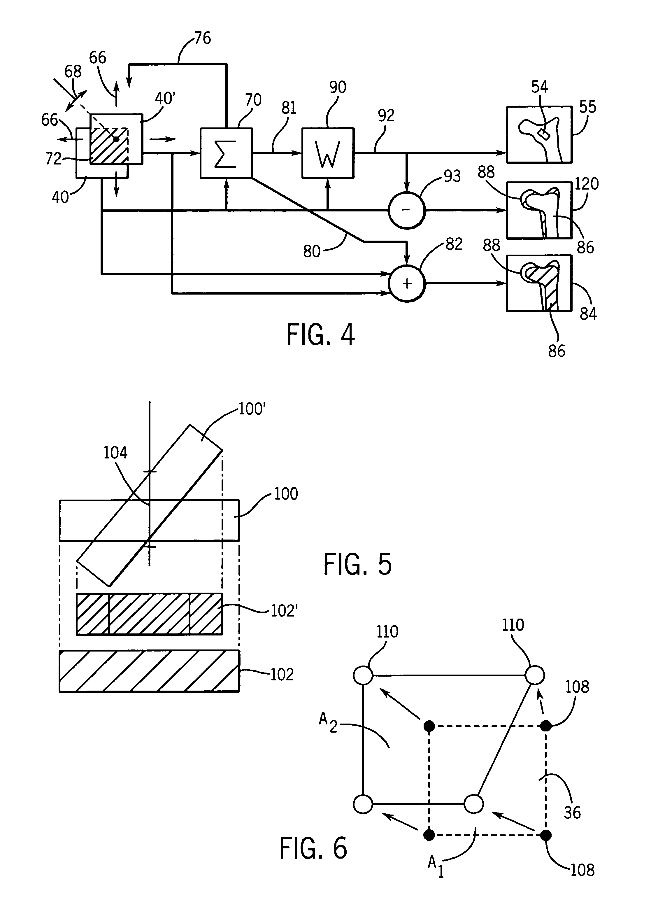
[0029] Referring now to FIG. 4 in a second embodiment, a more sophisticated comparison process provides first for an iterative translation 66 of image 40′ with respect to image 40 and a rotation 68 of image 40′ with respect to image 40 to maximize the correlation between bone pixels 36 in range 62 in the images 40 and 40′ as performed by correlation engine 70. The correlation engine 70, which may be realized in software, generally tallies the number of bone pixels in range 62 that overlap with bone pixels in image 40 at each iteration. This and the previous tally is used to generate a translation / rotation signal 76 that guides the translation and rotation process, for example, in a hill-climbing algorithm to approach the best alignment. As will be understood to those of ordinary skill in the art, the maximum allowed amount of translation 66 and rotation 68 may be constrained according to predefined limits and the correlation only considers an area of overlap 72 of the images 40 and ...


PUM


Abstract

An x-ray densitometry system provides improved analysis of bone images taken of a patient over a course of time by comparing the images to deduce positioning errors and / or to correct positioning errors for improved quantitative assessment of the bone.

Description

CROSS-REFERENCE TO RELATED APPLICATIONS [0001] This application is a continuation-in-part of U.S. application Ser. No. 10 / 065,109 filed Sep. 18, 2002, and hereby incorporated by reference.STATEMENT REGARDING FEDERALLY SPONSORED RESEARCH OR DEVELOPMENT [0002] -- BACKGROUND OF THE INVENTION [0003] The present invention relates generally to x-ray bone densitometers for measuring bone health and particularly a densitometer adapted to monitor changes in bone health of a patient over a period of time. [0004] X-ray bone densitometers make measurements at two x-ray energies to provide separate attenuation images of two basis materials, typically bone and soft tissue. The bone attenuation image is substantially free from attenuation caused by soft tissue allowing areal bone density (g / cm2) to be accurately determined in vivo for assessments of bone strength and health. The bone attenuation image also provides improved definition of bone outlines, allowing measurements, for example, of bone m...

Claims


Application Information

Patent Timeline
IPC IPC(8): A61B6/00G06T1/00
CPCA61B6/4035A61B6/505A61B6/482A61B6/4241
Inventor ZELLER, SCOTT STEVENSTEVENS, GRANT MOREYMARKWARDT, PAUL EUGENENORD, RUSSELL HARRYWASHENKO, ROBERTERGUN, DAVID LOWRY
Owner GENERAL ELECTRIC CO
Learn More