
Integral flexible spine stabilization device and method

a spine stabilization and flexible technology, applied in the field of integrated flexible spine stabilization devices and methods, can solve the problems of additional clinical problems, significant drawbacks of established methods of rigid spinal fusion, and need for additional surgery

Inactive Publication Date: 2005-05-05
BURTON CHARLES V
View PDF25 Cites 255 Cited by
  • Summary
  • Abstract
  • Description
  • Claims
  • Application Information

AI Technical Summary

Benefits of technology

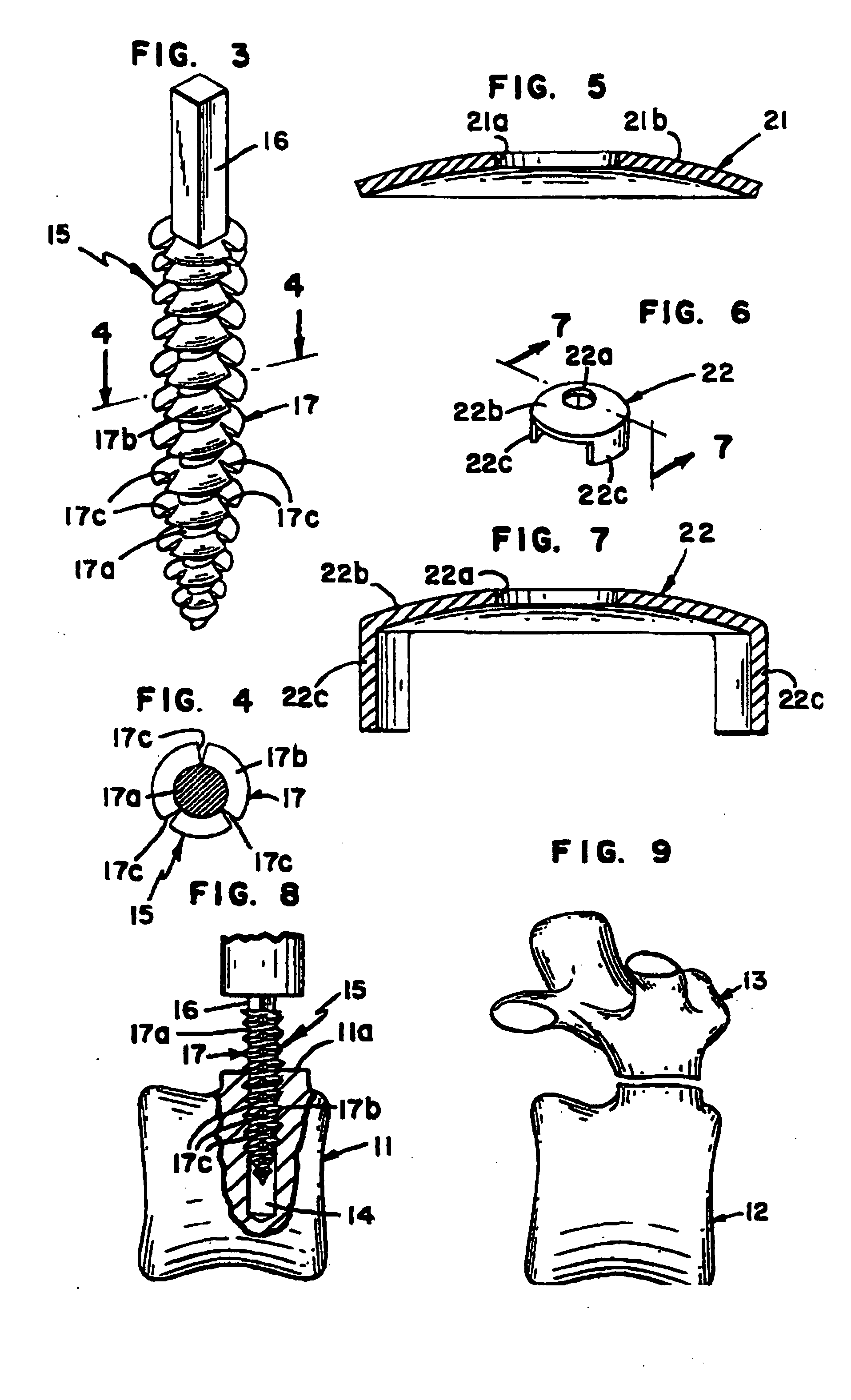
[0013] In one embodiment, the anchor means includes an upper shank portion and a lower threaded portion having a screw thread. The lower portion is cooperatively connected to the shank portion. The screw thread has segmented areas, wherein a rotary force may be applied to the shank portion whereby the threaded portion is driven into and secured into the pedicles. The screw thread may have segmented areas, wherein after a period of time the vertebra's bony re-growth encompasses the segmented areas to further secure the threaded portion to the pedicles.
[0015] In a more preferred embodiment, the anchor means and the stabilization means are of one-piece unitary construction. The anchor means has an upper portion and a lower portion. The upper portion is integral with the stabilization means. The lower portion forms an elongate post, insertable into a hole drilled into the pedicle of a vertebra. To promote ingrowth, the post is porous. Additionally, the post is smaller than the diameter of the drilled hole, leaving sufficient room for a desired quantity of a slurry paste formed from ground bone tissue that includes stem cells, thereby encouraging an ingrowth of bone tissue into the post. In an alternative embodiment the post is hollow forming a channel or lumen therethrough with the outer post areas being porous. This alternative embodiment is designed to promote additional cellular ingrowth.

Problems solved by technology

Established methods of rigid spinal fusion have significant drawbacks.
These adjacent vertebrae are subject to inordinately high stress and degeneration often leading to the need for additional surgery.
The stress patterns produced by fusion often also produce additional clinical problems relating to the sacroiliac and hip joints.
Safe, effective and more physiologic long-term stabilization has been difficult to accomplish.
When spine fusions involve mechanical instrumentation, significant adverse forces are directly aimed at the supportive sites whether they are bone screws, hooks, or the like.
This phenomenon usually wears away at the relatively soft bone matter, resulting a loosening of the attachment points for the implanted hardware and a resulting loss of support by this instrumentation.
These combined procedures involve extensive surgery, substantial blood loss and high cost very often creating more problems for the patient than those solved.
Further, the recovery time for such procedures is significant and debilitating and very often necessitates additional spinal surgery.
Therefore, the present management of spinal instability by instrumented fusion stabilization is not optimal.
In modern medical practice, the presence of large and dense metallic devices can be a significant liability due to the scattering artifacts generated if imaging, such as MRI, is attempted.
It was recognized that it would be virtually impossible to achieve these structural characteristics by artificial means.
These studies did not demonstrate significant ingrowth of osteoblasts into the coral and these observations led to the conclusion that coral showed little value in this regard.
However, self-tapping bone screws, though widely used for a variety of applications, typically struggle to provide both the strength sufficient enough to drive themselves into bone, and the porosity necessary to promote ingrowth.

Method used


Image

  • Integral flexible spine stabilization device and method
  • Integral flexible spine stabilization device and method
  • Integral flexible spine stabilization device and method

Examples


Embodiment Construction

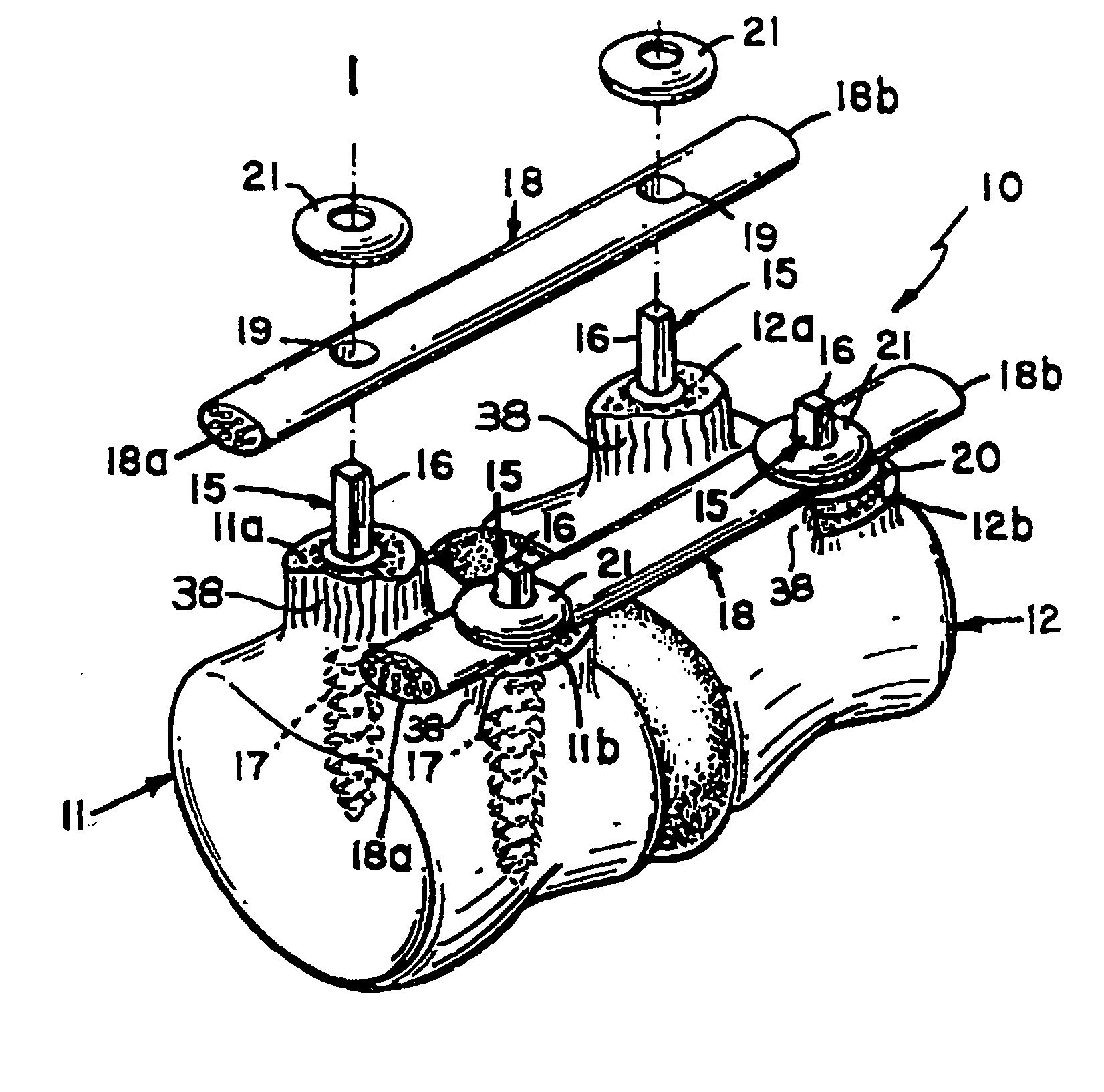
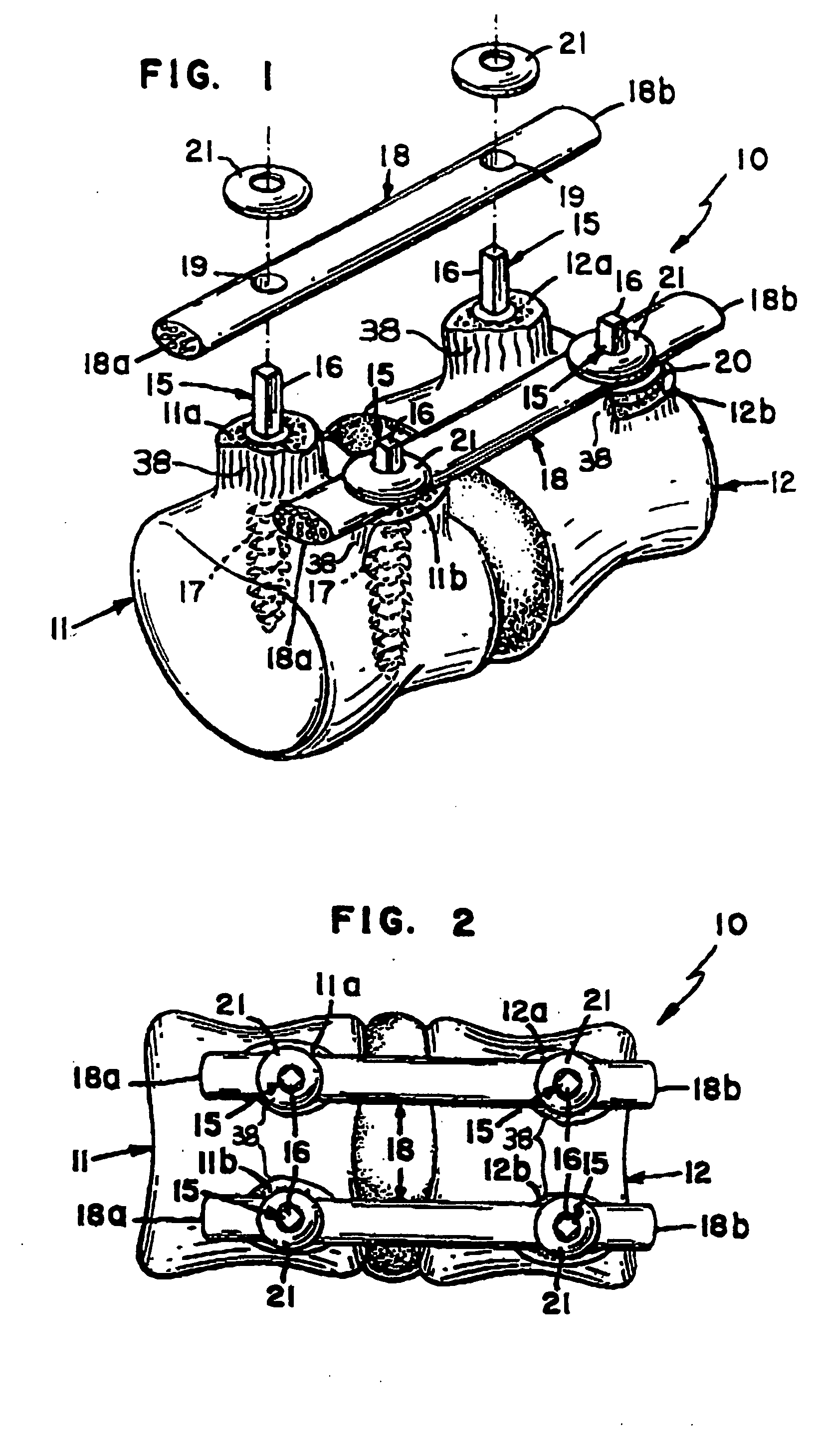
[0034] Referring to the figures, wherein like numerals represent like parts throughout the several views, there is generally illustrated a device 10 useable for stabilizing at least a portion of a vertebral column. In FIG. 1, a first vertebra 11 and second vertebra 12 are shown. It should be understood that when the terms “first and second” vertebrae are used in this application, reference is being made only to vertebrae that are adjacent, and not to any specific vertebrae along the vertebral column. Each vertebra has a posterior element, designated as 13 shown in FIG. 9. When the posterior element 13 is removed from the vertebra, a first and second vertebral pedicle is exposed in each vertebra. FIG. 1 shows the first vertebral pedicle 11a and the second vertebral pedicle 11b of the first vertebra 11 and the first vertebral pedicle 12a and the second vertebral pedicle 12b of the second vertebra 12. If screws are used as anchoring devices, each of the pedicles (11a, 11b, 12a or 12b) ...


PUM


Abstract

Provided are a device and a method for stabilizing two or more vertebrae by joining the vertebrae with a flexible device. The flexible device is of unitary construction and includes anchor posts constructed and arranged for insertion into holes drilled into the vertebrae, preferably after removing all or a portion of the pedicles from the target vertebrae. Removal of the pedicles provides an acceptable fastening site, prevents interference with the device by the pedicles, and provides native donor bone tissue, thereby obviating the need for a second surgery to harvest bone tissue from a different site, such as the hip.

Description

[0001] This application provides a method and device useable to flexibly connect at least two vertebrae together, thereby increasing the stability of the vertebral column, and also allow for the adequate decompression of pinched nerves. The present invention improves upon related devices and methods, invented by the Applicant, and fully described in U.S. Pat. No. 4,743,260 and U.S. Pat. No. 5,282,863. The contents of these patents are incorporated by reference herein in their entireties.BACKGROUND OF THE INVENTION [0002] Stabilization of the spinal vertebrae has traditionally been accomplished using fusion, a long-practiced procedure involving the permanent and rigid fixation of one or more spinal segments. Each spinal segment includes two adjacent vertebrae, their posterior bony elements, an intervertebral disc between the two vertebrae, ligaments, and two facet joint capsules. Stabilizing two or more vertebrae together is done in an attempt to improve spinal stability and prevent ...

Claims


Application Information

Patent Timeline
IPC IPC(8): A61B17/70A61B17/80
CPCA61B17/70A61B17/7002A61B17/7007A61B17/809A61B17/7031A61B17/7032A61B17/701
Inventor BURTON, CHARLES V.
Owner BURTON CHARLES V
Learn More