Endovascular prosthesis

a prosthesis and endovascular technology, applied in the field of endovascular prosthesis, can solve the problems of stroke, paralysis or abnormal sensation, high risk for patients,

Inactive Publication Date: 2005-05-05
MAROTTA THOMAS R +1
View PDF12 Cites 72 Cited by
  • Summary
  • Abstract
  • Description
  • Claims
  • Application Information

AI Technical Summary

Benefits of technology

[0041] The present endovascular prosthesis is believed to be particularly useful in the treatment of aneurysms such as those described hereinabove and is therefore believed to provide a significant alternative to the conventional surgical techniques described hereinabove. Additionally, it is envisaged that the present endovascular prosthesis may be used in the treatment of certain aneurysms which are diagnosed as being inoperable. The present endovascular prosthesis

Problems solved by technology

While aneurysms can occur in any artery of the body, it is usually those which occur in the brain which lead to the occurrence of a stroke.
Aneurysms also can cause problems which are not related to bleeding although this is less common.
Further, the aneurysm can also press against nerves (this has the potential of resulting in paralysis or abnormal sensation of one eye or of the face) or the adjacent brain (this has the potential of resulting in seizures).
Unfortunately, surgical techniques for treating these conditions are regarded as major surgery involving high risk to the patient and necessitate that the patient have strength even to have a chance to survive the procedure.
While these endovascular approaches are an advance in the art, they are disadvantageous.
Specifically, the risks of these endovascular approaches include rupturing the aneurysm during the procedure or causing a stroke due to distal embolization of the device or clot from the aneurysm.
Additionally, concern exists regarding the long term results of endovascular aneurysm obliteration using these techniqu

Method used


Image

  • Endovascular prosthesis
  • Endovascular prosthesis
  • Endovascular prosthesis

Examples


Embodiment Construction

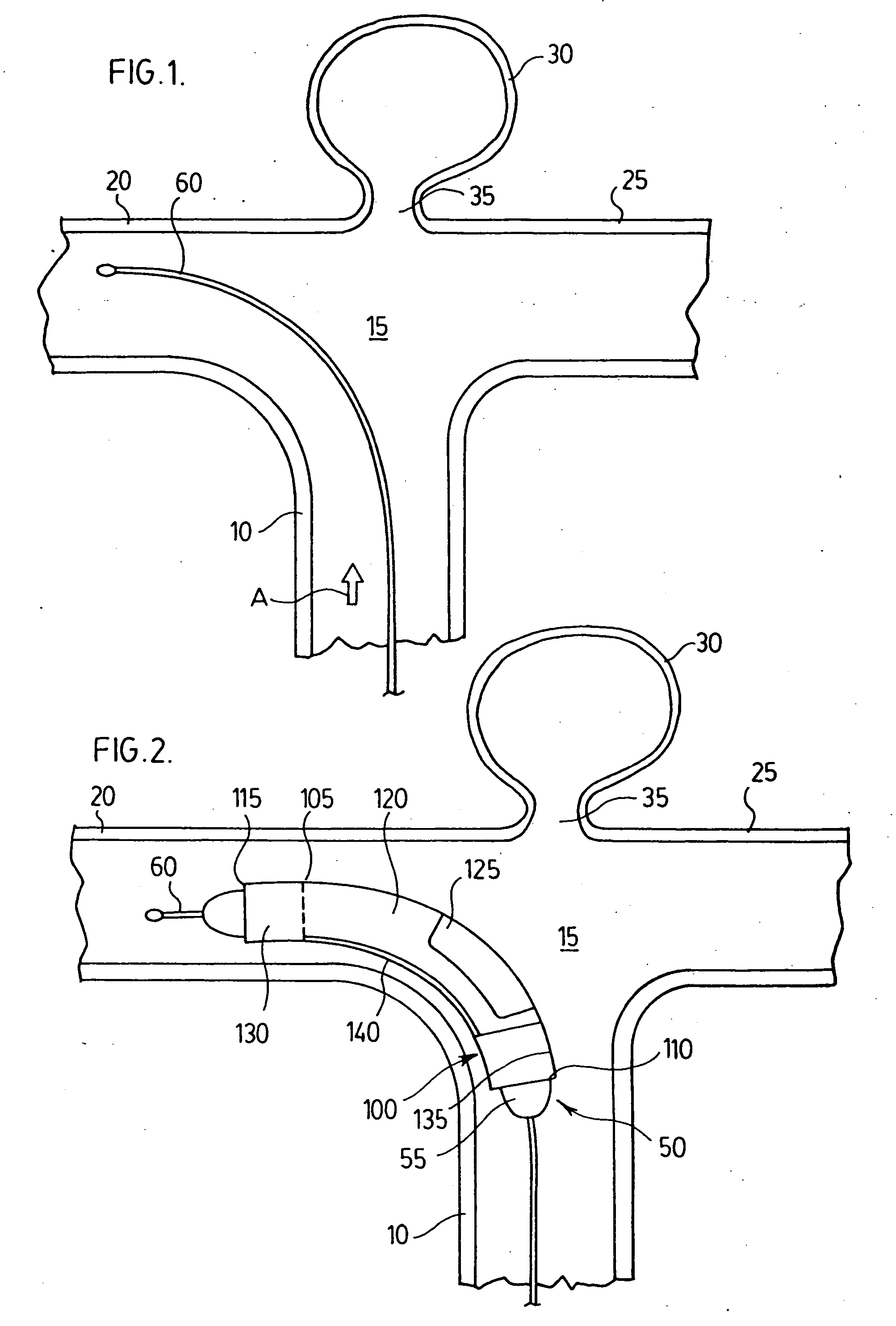
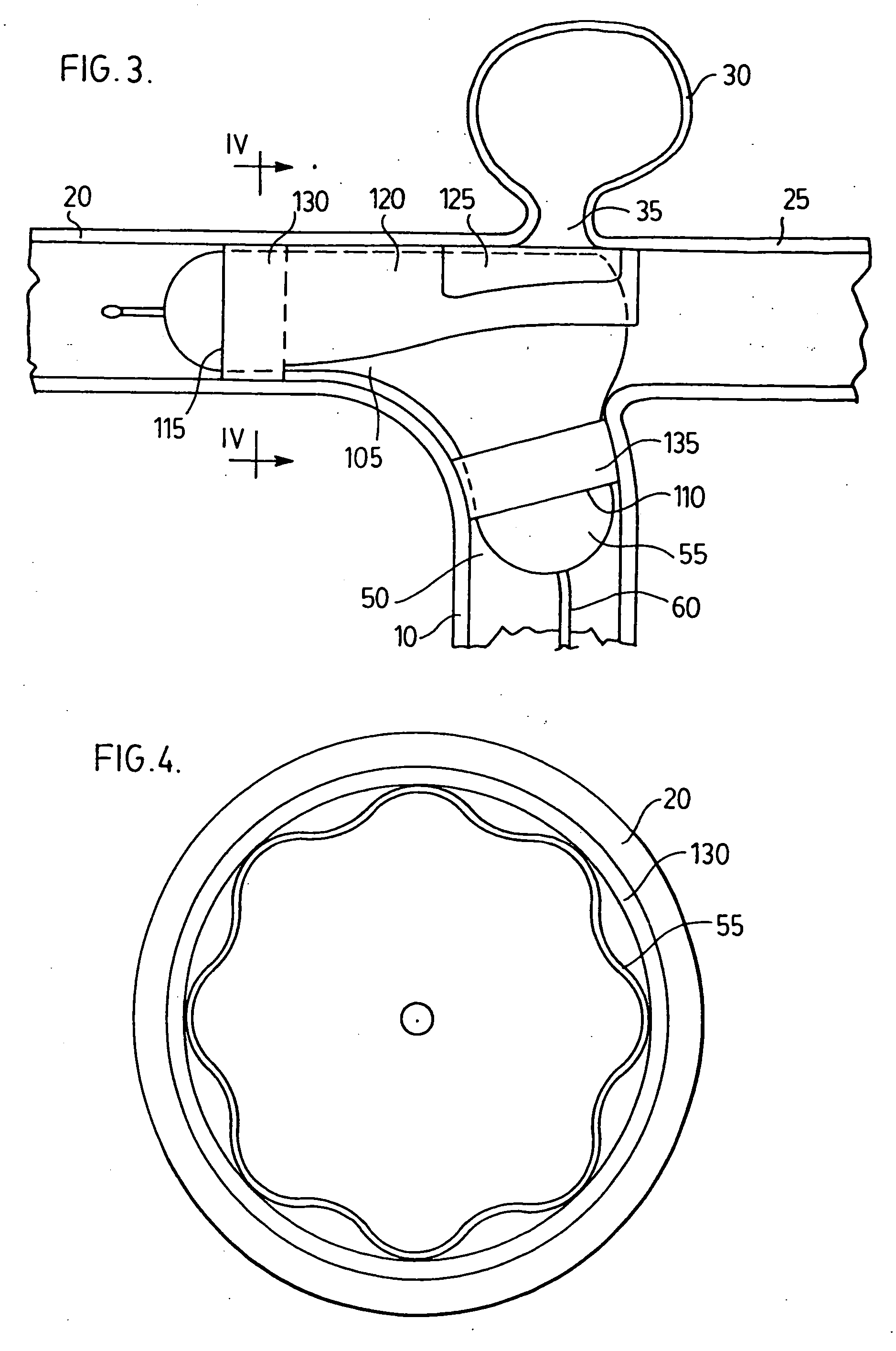
[0052] With reference to FIGS. 1-4, a first embodiment of the present endovascular prosthesis will be described with particular reference to implantation of same at the terminal bifurcation of the basilar artery.

[0053] Thus, there is illustrated a basilar artery 10 which terminates at a junction 15 which bifurcates into pair of secondary arteries 20,25. Located at junction 15 is an aneurysm 30. Aneurysm 30 has an opening 35 (shown enlarged for illustrative purposes only) through which blood enters and sustains aneurysm 30.

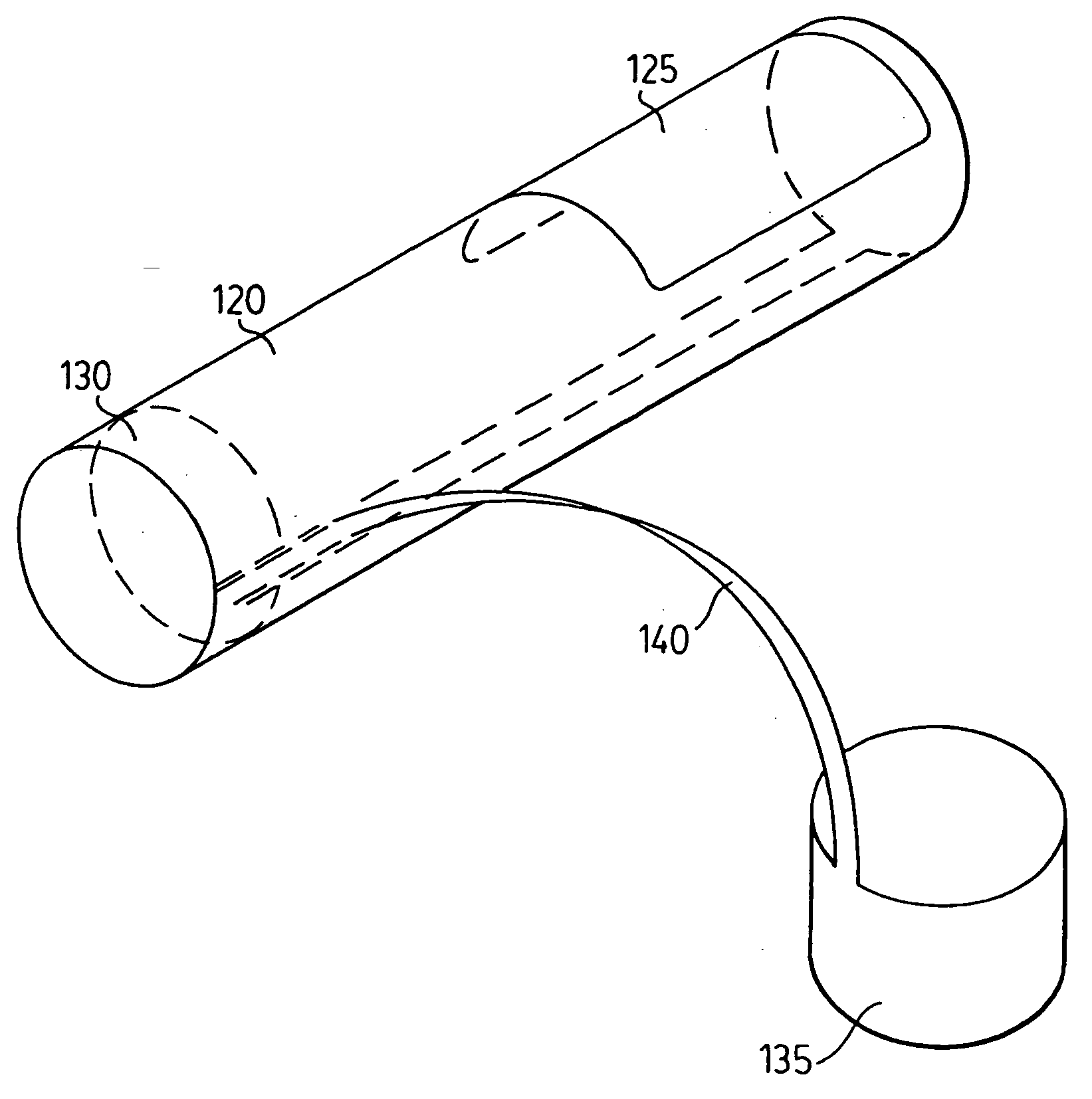
[0054] An endovascular prosthesis 100 is mounted on a catheter 50.

[0055] Catheter 50 comprises an inflatable balloon 55 and a guidewire 60. Catheter 50, inflatable balloon 55 and guidewire 60 are conventional. As is known in the art, inflatable balloon 55 is moveable along guidewire 60.

[0056] Endovascular prosthesis 100 is constructed of a body 105. Body 105 comprises a proximal end 110 and a distal end 115. Endovascular prosthesis 100 further comprises an expa...


PUM


Abstract

An expandable endovascular prosthesis comprising: body having a proximal end and a distal end; a first expandable portion disposed between the proximal end and the distal end, the tubular first expandable portion being expandable from a first, unexpanded state to a second, expanded state with a radially outward force thereon to urge the first expandable portion against a vascular lumen; and a second expandable portion attached to the first tubular expandable portion; the second expandable portion being expandable upon expansion of the tubular first expandable portion. The endovascular prosthesis is particularly useful in the treatment of aneurysms, particularly saccular aneurysms. Thus, the first expandable portion serves the general purpose of fixing the endovascular prosthesis in place at a target vascular lumen or body passageway in the vicinity at which the aneurysm is located and, upon expansion of the first expandable portion, the second expandable portion expands to block the aneurysmal opening thereby leading to obliteration of the aneurysm. A method of delivering and implanting the endovascular prosthesis is also described.

Description

BACKGROUND OF THE INVENTION [0001] 1. Field of the Invention [0002] In one of its aspects, the present invention relates to an endovascular prosthesis. In another of its aspects, the present invention relates to a method of treating an aneurysm in a patient. [0003] 2. Description of the Prior Art [0004] As is known in the art, an aneurysm is an abnormal bulging outward in the wall of an artery. In some cases, the bulging may be in the form of a smooth bulge outward in all directions from the artery—this is known as a “fusiform aneurysm”. In other cases, the bulging may be in the form of a sac arising from an arterial branching point or from one side of the artery—this is known as a “saccular aneurysm”. [0005] While aneurysms can occur in any artery of the body, it is usually those which occur in the brain which lead to the occurrence of a stroke. Most saccular aneurysms which occur in the brain have a neck which extends from the cerebral blood vessel and broadens into a pouch which ...

Claims


Application Information

Patent Timeline
IPC IPC(8): A61F2/06A61F2/82
CPCA61F2/844A61F2/856A61F2/91A61F2/915A61F2/958A61F2002/065Y10T29/49863A61F2002/825A61F2002/91525A61F2002/91533A61F2002/91575A61F2230/0095A61F2002/823
Inventor MAROTTA, THOMAS R.RICCI, DONALD R.
Owner MAROTTA THOMAS R
Why Eureka
Try Eureka