Clutch device, motor apparatus and wiper system

a technology of clutch device and wiper arm, which is applied in the direction of slip coupling, vehicle cleaning, gearing, etc., can solve the problems of excessively large external force applied to the wiper blade and the wiper arm, the damage of the joint member connected to the swing arm or the worm wheel, and the damage of the joint member, so as to achieve the effect of limiting damag

Active Publication Date: 2005-05-12
DENSO CORP
View PDF18 Cites 26 Cited by
  • Summary
  • Abstract
  • Description
  • Claims
  • Application Information

AI Technical Summary

Benefits of technology

[0014] The present invention addresses the above disadvantages. Thus, it is an objective of the present invention to provide a clutch device, a motor apparatus and a wiper system, which can limit damage to its component and burnout of the motor apparatus and which can automatically return the clutch device to its initial position by operating a motor s

Problems solved by technology

Therefore, the joint member, which is connected to the swing arm, or the worm wheel, which is connected to the joint member, could be damaged by the external force.
However, an excessively large external force could be applied to, for example, the wiper blade and the wiper arm even in a case where the wiper blade and the wiper arm are not placed outside of the predetermined reciprocal rotational angular range.
In other words, the excessively large external force could be applied to, for example, the wiper blade and the wiper arm even in the case where the wiper blade and the wiper arm are operated within the predetermined reciprocal rotational angular range (a normal wiping range).
In such a case, the wiper blade and the wiper arm are arrested by the fallen heavy snow or receive an excessively large external force from the fallen snow.
Therefore, the exce

Method used


Image

  • Clutch device, motor apparatus and wiper system
  • Clutch device, motor apparatus and wiper system
  • Clutch device, motor apparatus and wiper system

Examples


first embodiment

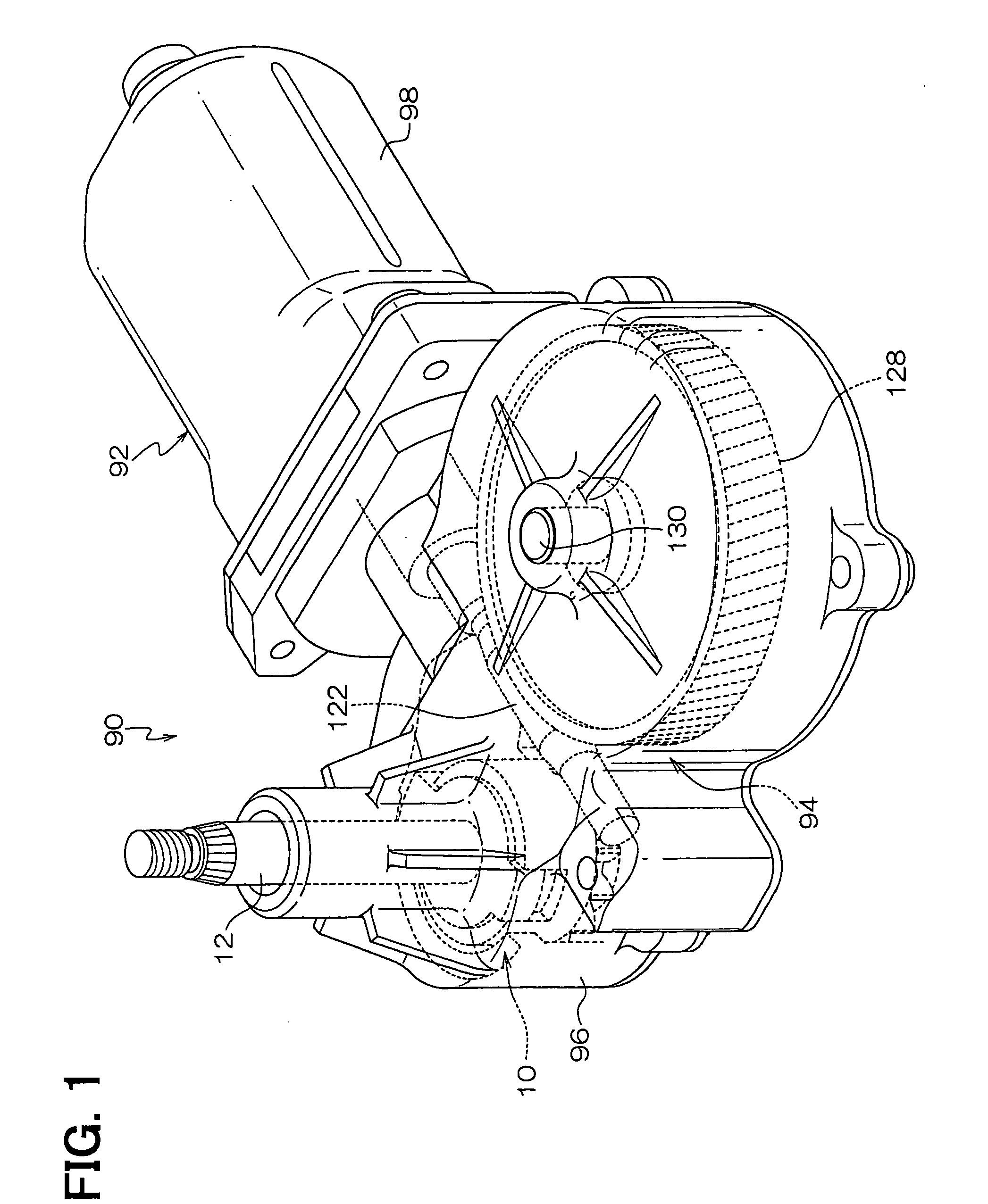
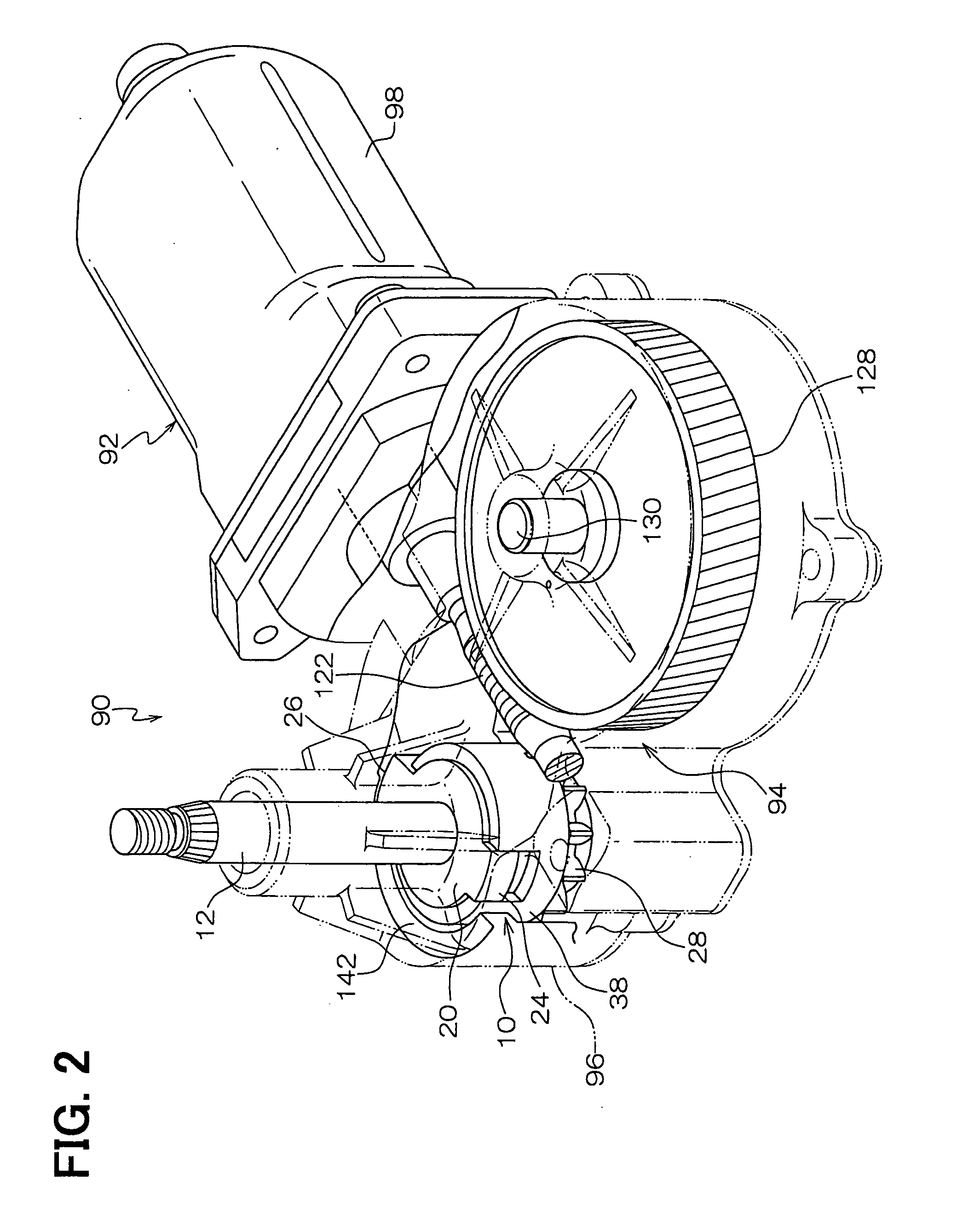
[0043]FIGS. 1 and 2 are perspective views of an entire wiper motor apparatus 90, in which a clutch device 10 of a first embodiment of the present invention is installed. The wiper motor apparatus 90 is formed as a wiper drive motor apparatus for driving a wiper system of a vehicle and includes a clutch device 10, a motor main body 92 and a motion converting mechanism (also referred to as a swing mechanism) 94.

[0044] The clutch device 10 includes an output shaft 12. A base end portion (a rear end portion) of the output shaft 12 includes a rotation restraining portion 14, a removal limiting portion 16 and a relatively rotatable shaft portion 18. The rotation restraining portion 14 includes a plurality of axial ridges 14a. The removal limiting portion 16 is formed in a rear end of the rear end portion of the output shaft 12. The relatively rotatable shaft portion 18 is arranged between the rotation restraining portion 14 and the removal limiting portion 16.

[0045] A clutch base (a bas...

second embodiment

[0106]FIG. 20 is a perspective exploded view of a clutch device 60 according to a second embodiment of the present invention.

[0107] The clutch device 60 has a structure, which is basically the same as that of the clutch device 10 of the first embodiment. However, the clutch device 60 includes a clutch base 62 in place of the clutch base 20 and also includes a clutch disk (the second rotatable member) 64 in place of the clutch disk 38.

[0108] The clutch base 62 is formed into a cup shape and includes a base wall 68 and a peripheral wall 70. A support hole 66, which corresponds to the output shaft 12, is formed through the base wall 68. The peripheral wall 70 extends from a peripheral edge of the base wall 68 in the axial direction of the output shaft 12. The support hole 66 is secured to the rotation restraining portion 14 of the output shaft 12, so that the clutch base 62 rotates integrally with the output shaft 12. Fitting female guide portions 72, 74 are provided in an opening si...

third embodiment

[0128]FIG. 21 is a cross sectional view of a motor apparatus 150 according to a third embodiment of the present invention.

[0129] The motor apparatus 150 has a structure, which is basically the same as that of the wiper motor apparatus 90 of the first embodiment. The motor apparatus 150 includes a motor main body 92, a motion converting mechanism 152 and a clutch device 154.

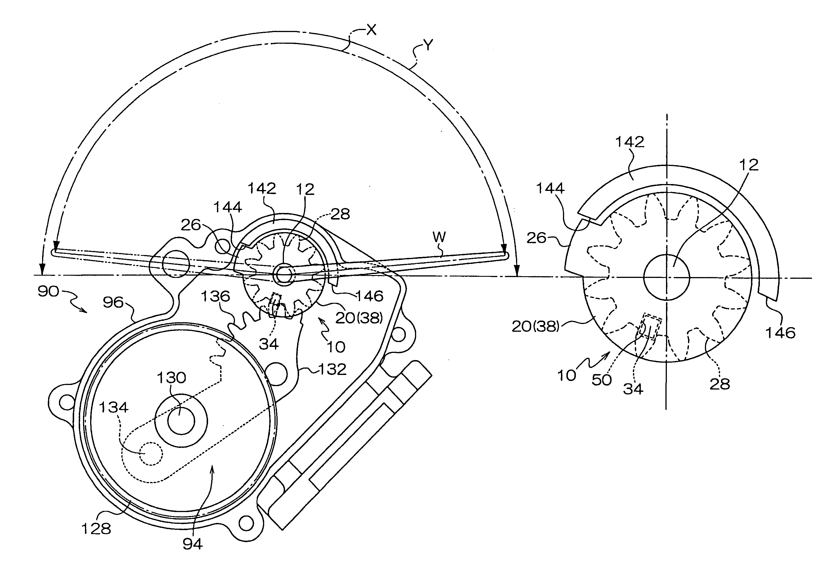
[0130] The motor main body 92 has the structure, which is substantially the same as that of the motor main body 92 of the first embodiment. In the first embodiment, the motor main body 92 (the armature 108) is rotated in the single direction. In contrast, in the present embodiment, the motor main body 92 is rotated in the normal direction and in the reverse direction between the rotation limiters 144, 146 of the stopper projection 142.

[0131] In the motion converting mechanism 152, the sector gear 132 and the holding lever 138 of the first embodiment are eliminated. Thus, the motor converting mechanism 152 inclu...


PUM


Abstract

Initiation of coupling between an input disk and a clutch disk at a maximum rotational coupling force without making relative rotation between the input disk and the clutch disk is enabled only when the output shaft is placed in a single engageable point within a normal reciprocal angular range of the output shaft. When a load applied to the output shaft is equal to or greater than a predetermined value, the input disk and the clutch disk are decoupled from one another, so that the relative rotation is made between the input disk and the clutch disk.

Description

CROSS REFERENCE TO RELATED APPLICATION [0001] This application is based on and incorporates herein by reference Japanese Patent Application No. 2003-378502 filed on Nov. 7, 2003 and Japanese Patent Application No. 2004-232554 filed on Aug. 9, 2004. BACKGROUND OF THE INVENTION [0002] 1. Field of the Invention [0003] The present invention relates to a clutch device, a motor apparatus and a wiper system. [0004] 2. Description of Related Art [0005] For example, a wiper system, which wipes a window glass of a vehicle, has a motor apparatus as its drive source. [0006] The wiper motor apparatus, particularly a rear wiper motor apparatus, includes a worm wheel, a swing arm and a joint member. The worm wheel is meshed with a rotatable shaft of an armature, which is rotatably supported by a case. The swing arm is connected to a wiper shaft. One end of the joint member is connected to a predetermined point of the worm wheel, and the other end of the joint member is connected to the swing arm. ...

Claims


Application Information

Patent Timeline
IPC IPC(8): B60S1/08B60S1/16F16D7/04F16D43/26F16H1/16F16H35/10H02K7/10H02K7/116
CPCB60S1/166Y10T74/19828F16D7/044
Inventor YAGI, HIDEYUKIIMAMURA, TAKAYUKI
Owner DENSO CORP
Why Eureka
Try Eureka