Mulcher with improved tooth design

a mulcher and tooth technology, applied in mechanical machines/dredgers, tilling equipment, grain treatment, etc., can solve the problems of difficult and cumbersome mounting assembly of the tooth assembly b>30/b> to the rotatable shaft b>22/b>, and achieve the effect of improving the cutting efficiency and cost effectiveness of labor and/or replacement parts

a mulcher and tooth technology, applied in mechanical machines/dredgers, tilling equipment, grain treatment, etc., can solve the problems of difficult and cumbersome mounting assembly of the tooth assembly b>30/b> to the rotatable shaft b>22/b>, and achieve the effect of improving the cutting efficiency and cost effectiveness of labor and/or replacement parts

US20050098331A1Active Publication Date: 2005-05-12PALADIN BRANDS GROUP

Image

  • Mulcher with improved tooth design
  • Mulcher with improved tooth design
  • Mulcher with improved tooth design

Examples


Embodiment Construction

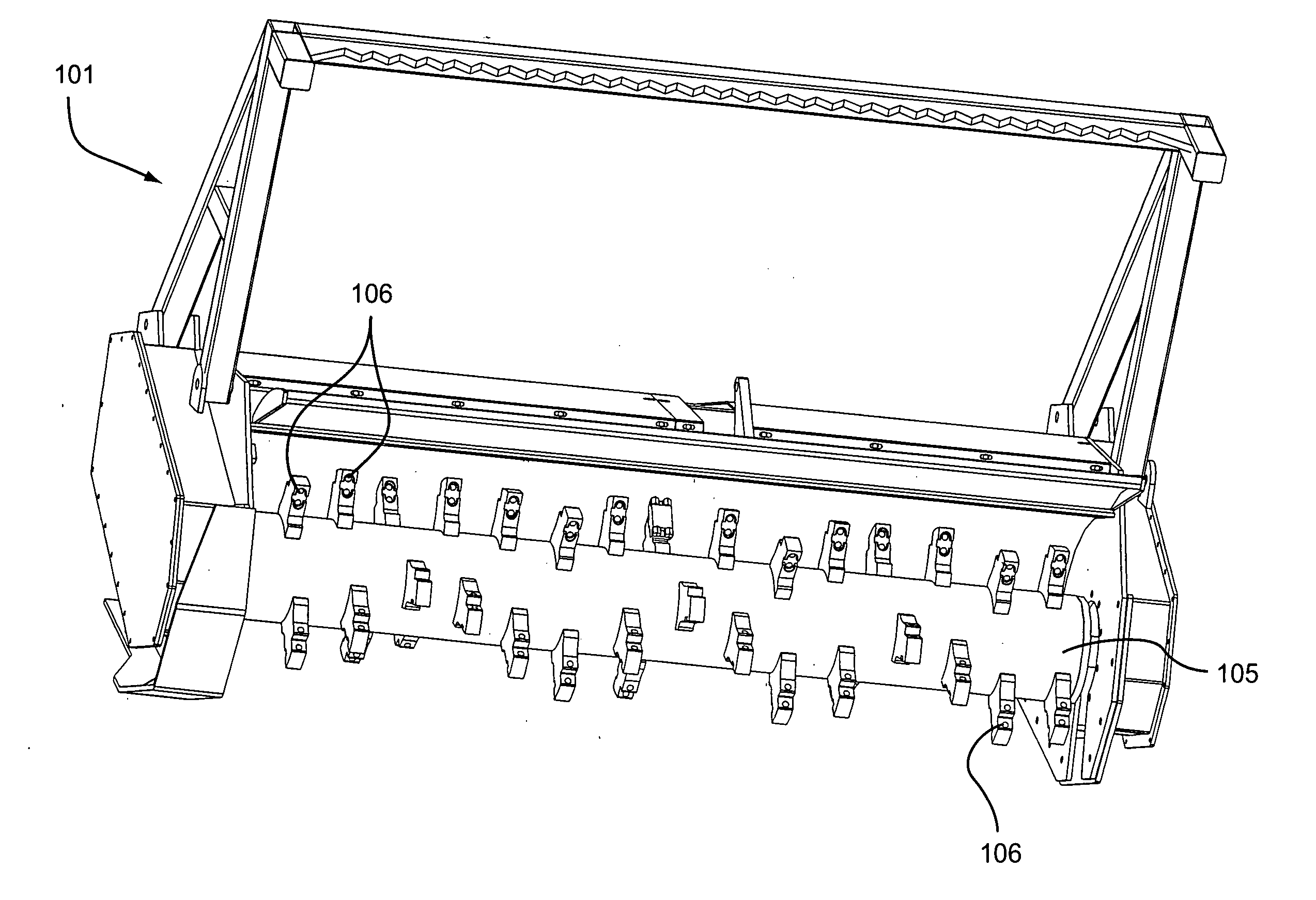
[0109]FIG. 6 illustrates a portion of a mulcher apparatus 100 according to one embodiment of the present invention. In this specification, the term mulcher apparatus is intended to be inclusive of grinders, wood chippers, tub grinders and horizontal grinders, etc. The mulcher apparatus 100 includes a tractor, for example, as shown in relation to FIG. 1. The mulcher apparatus 100 includes a mulching unit 101 that includes a rotor 105, e.g., in the form of a solid or hollow cylindrical drum, and a plurality of tooth assemblies 106 each having a holder 110 and a cutter element 115. Each of the holders 110 is mounted to the rotor 105, e.g., by welding. However, the holders 110 may be attached to the rotor 105 in a manner which is similar to that shown and described in relation to FIG. 2. Each holder 110 is structured to support the cutter element 115 along the bottom and / or rear walls thereof, e.g., the holder forms a step like configuration where the cutter element 115 may be supported...


PUM


Abstract

A mulcher apparatus includes a tractor and a mulcher unit provided to the tractor. The mulcher unit includes a tooth assembly with a holder and a cutter element with a cooperating notch portion and cross bar arrangement. The notch portion can be retrofit to existing holder arrangements. The cutter element may include various features, to enhance cutting efficiency. For example, the cutter elements may include a double-ended structure, angle tab portions at each corner portion, carbide coatings, a pair of tip portions at each end with a space therebetween, and / or a generally H-shaped configuration.

Description

CROSS REFERENCE TO PRIORITY APPLICATION [0001] This application claims the benefit of U.S. Provisional Application No. 60 / 515,433, filed Oct. 30, 2003, incorporated by reference in its entirety.BACKGROUND OF THE INVENTION [0002] 1. Field of the Invention [0003] This invention relates to an industrial mulcher apparatus for use in mulching vegetation such as brush, trees, etc., or stump grinding. In particular, the invention relates to improvements to a mulcher unit including a plurality of cutter assemblies that serially engage and mulch the intended vegetation in rapid fashion. [0004] 2. Description of Related Art [0005]FIGS. 1-5 illustrate a related art mulcher apparatus 10. The mulcher apparatus 10 includes a tractor 12 supported on a set of wheels 14. A tractor driver can sit within a protected cage 16 positioned on a frame of the mulcher apparatus 10. A hydraulic unit 18 connected to the tractor 12 provides structure by which a mulcher unit 20 is positioned, e.g., laterally shif...

Claims


Application Information

Patent Timeline
12 May 2005
Publication
US20050098331A1
IPC
A01G3/00; E02F3/24; E02F9/28
CPC
A01B33/103; A01G3/002; E02F9/2866; E02F3/241; B02C18/18; A01G23/067; E02F3/186; E02F5/282
Inventors
EDWARDS, JOHN W.