Micromechanical structural element having a diaphragm and method for producing such a structural element

a technology of structural elements and diaphragms, which is applied in the direction of instruments, liquid/fluent solid measurements, volume/mass flow by differential pressure, etc., can solve the problems of very fragile structural elements created, very time-consuming and critical back process, etc., and achieve great stability

Active Publication Date: 2005-05-12
ROBERT BOSCH GMBH
View PDF15 Cites 151 Cited by
  • Summary
  • Abstract
  • Description
  • Claims
  • Application Information

AI Technical Summary

Benefits of technology

[0006] The exemplary embodiment and/or exemplary method of the present invention provides a way to implement a micro

Problems solved by technology

This back process is very time-intensive and critical with respect to yield, because one has to etch all the way

Method used


Image

  • Micromechanical structural element having a diaphragm and method for producing such a structural element
  • Micromechanical structural element having a diaphragm and method for producing such a structural element
  • Micromechanical structural element having a diaphragm and method for producing such a structural element

Examples


Embodiment Construction

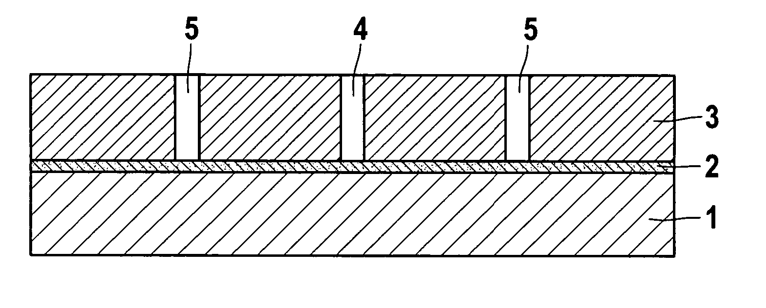
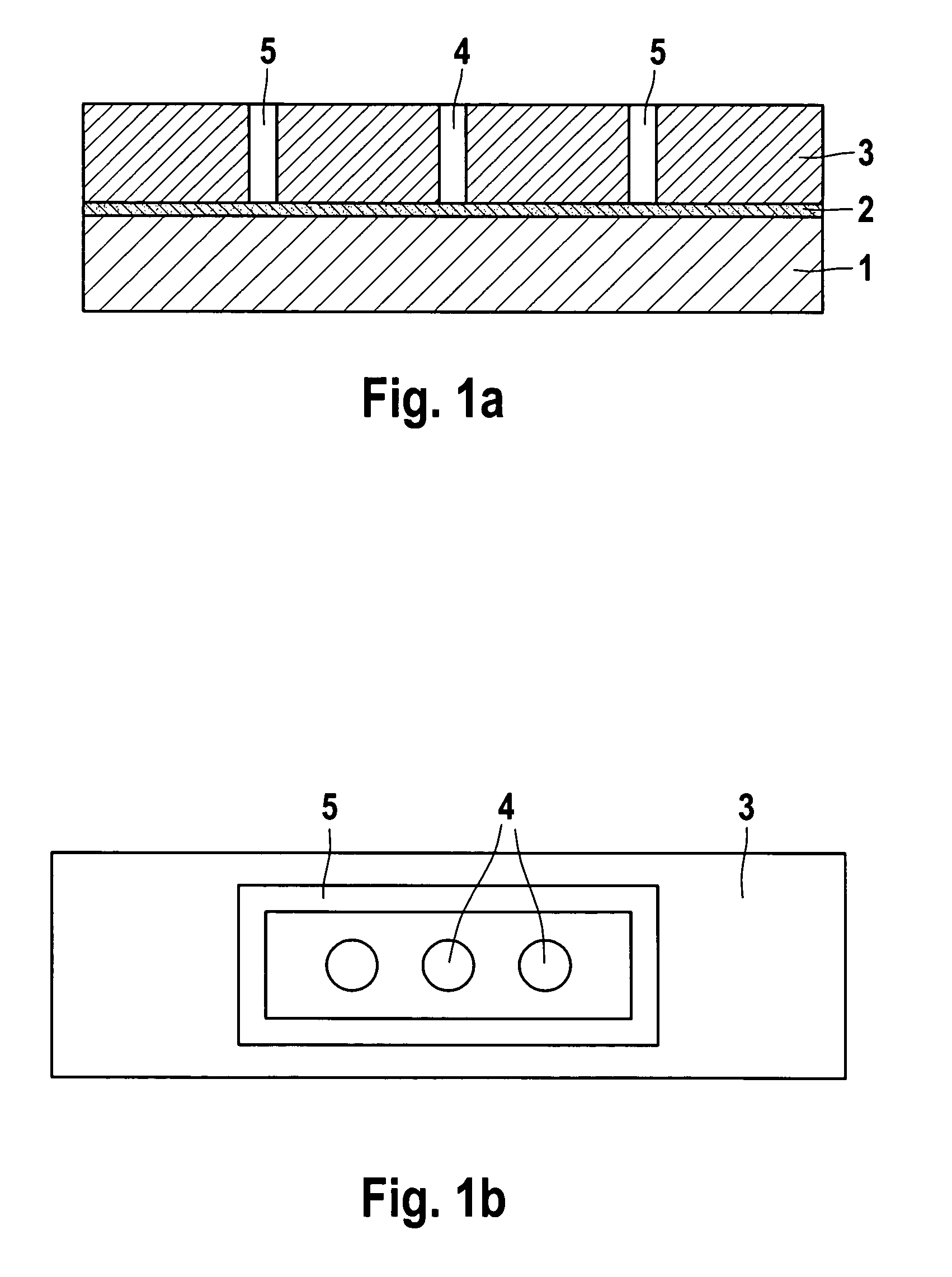
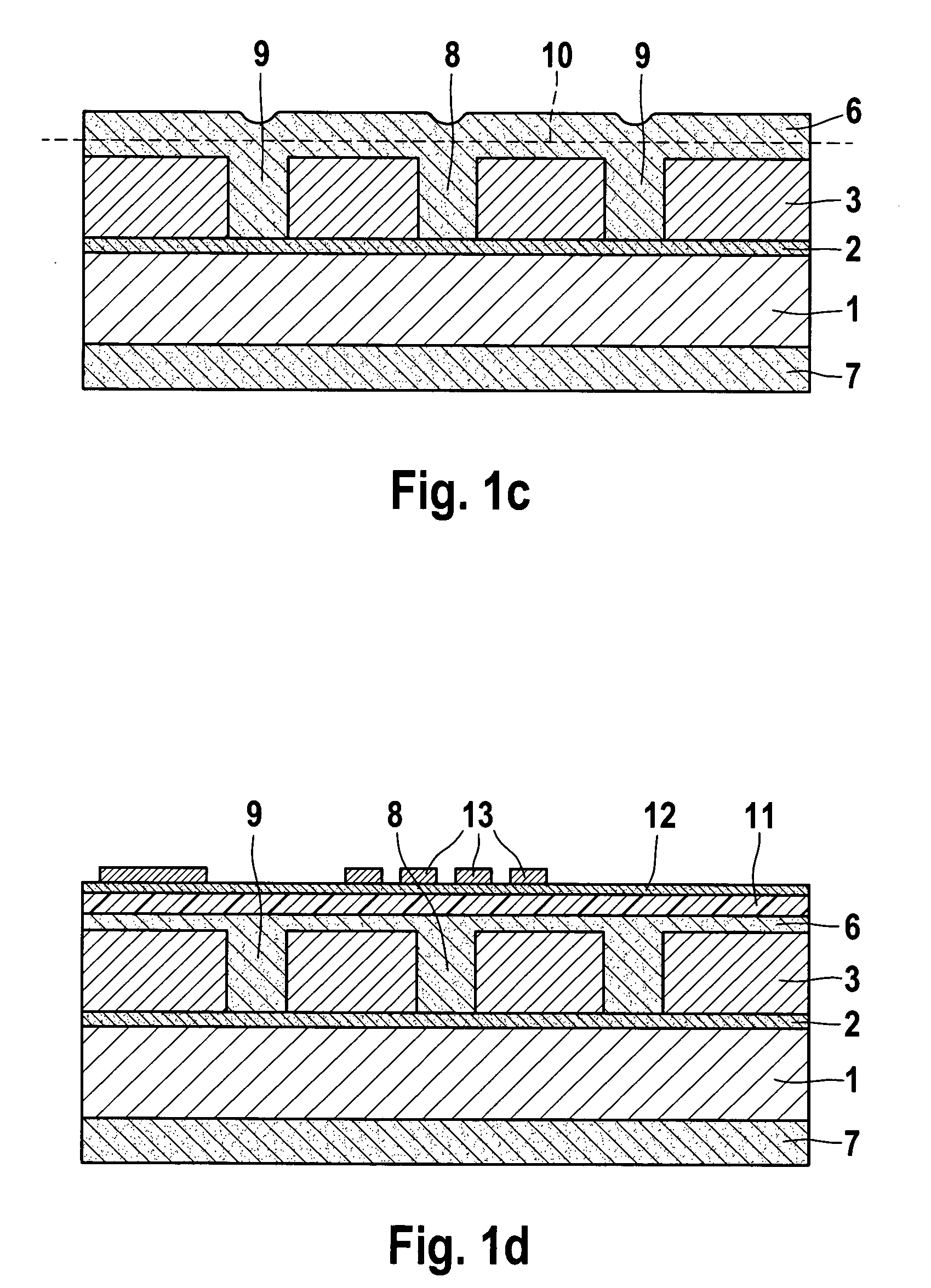
[0055] The method variant for producing a micromechanical structural element having a diaphragm, shown in FIGS. 1a through 1g, starts out either from a silicon wafer 1, on which first of all a silicon oxide layer 2 and then a monocrystalline or polycrystalline silicon layer or germanium layer 3 has been deposited, or from an SOI (silicon on insulator) wafer whose construction usually includes a monocrystalline or polycrystalline silicon layer 3, which is connected to a silicon substrate 1 via a silicon oxide layer 2. Silicon oxide layer 2 will be denoted below as etch stop layer 2, and silicon layer or germanium layer 3 as sacrificial layer 3.

[0056] Corresponding to the exemplary method according to the present invention, sacrificial layer 3 is structured, at least one recess 4 being generated for a stabilizing element. In the method variant shown in FIGS. 1a through 1g, the structuring of the sacrificial layer takes place in a trench process. In this context, besides a recess 4 fo...


PUM

PropertyMeasurementUnit
Pressureaaaaaaaaaa
Structureaaaaaaaaaa
Electrical conductoraaaaaaaaaa

Abstract

A micromechanical structural element, having a very stable diaphragm, implemented in a pure front process and in a layer construction on a substrate. The layer construction includes at least one sacrificial layer and one diaphragm layer above the sacrificial layer, which is structured for laying bare the diaphragm and generating stabilizing elements on the diaphragm, at least one recess being generated for a stabilizing element of the diaphragm. The structure generated in the sacrificial layer is then at least superficially closed with at least one material layer being deposited above the structured sacrificial layer, this material layer forming at least a part of the diaphragm layer and being structured to generate at least one etch hole for etching the sacrificial layer, which is removed from the region under the etch hole, the diaphragm and the at least one stabilizing element being laid bare, a cavity being created under the diaphragm.

Description

FIELD OF THE INVENTION [0001] The present invention relates to a micromechanical structural element having at least one diaphragm, the structural element structure being implemented in a layer construction on a substrate. The layer construction includes at least one sacrificial layer and one diaphragm layer above the sacrificial layer. The diaphragm is developed in the diaphragm layer in that under the diaphragm a cavity is developed in the sacrificial layer. The present invention is also directed to a method for producing such a micromechanical structural element. For laying bare the diaphragm, at least one etch hole is generated in at least one material layer above the sacrificial layer, this at least one material layer forming at least one layer structural element of the diaphragm layer. The material of the sacrificial layer is then removed in an isotropic etching step in the region below the etch hole, this bringing about a cavity. BACKGROUND INFORMATION [0002] Micromechanical s...

Claims


Application Information

Patent Timeline
IPC IPC(8): B81B3/00B81C1/00H01L21/00H01L27/14
CPCB81B3/007B81C2201/0167B81B2203/0127B81B2201/0264
Inventor FUERTSCH, MATTHIASPINTER, STEFANWEBER, HERIBERTFISCHER, FRANKMETZGER, LARSSCHELLING, CHRISTOPHSUNDERMEIER, FRIEDER
Owner ROBERT BOSCH GMBH
Why Eureka
Try Eureka