
Systems and methods for automatic carburetor enrichment during cold start

a technology of automatic carburetor and cold start, which is applied in the direction of carburettors, fuel injection control, engine components, etc., can solve the problems of difficult to create a sufficient amount of fuel vapor, and the system of u.s. pat. no. 5 cannot provide an enriched air-fuel mixtur

Inactive Publication Date: 2005-05-12
BOMBARDIER RECREATIONAL PROD INC
View PDF11 Cites 18 Cited by
  • Summary
  • Abstract
  • Description
  • Claims
  • Application Information

AI Technical Summary

Benefits of technology

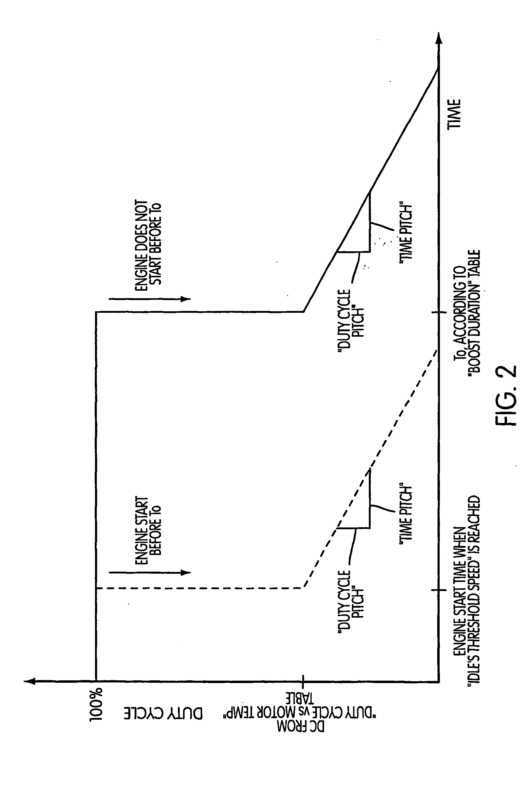
[0013] A method according to the present invention for controlling the air-fuel ratio of an air fuel mixture supplied to a carburetor of an internal combustion engine during cold start, the engine having a carburetor including a fuel bowl, a fuel line between the fuel reservoir and an induction passage of the carburetor, and a solenoid valve disposed in the fuel line, includes determining a temperature of the engine, determining a duty cycle of the solenoid valve associated with the determined temperature, setting the duty cycle of the solenoid valve to the associated duty cycle at an engine start time to increase the air-fuel ratio of the air-fuel mixture at engine start.

Problems solved by technology

The control system of U.S. Pat. No. 5,021,198 cannot provide an enriched air-fuel mixture during cold start
When the engine is cold it is difficult to start because it is difficult to create a sufficient amount of fuel vapor in the combustion chamber because atomization and vaporization are less effective at lower temperatures.
While completely reliable during operation, condensation of fuel, oil, and water in the air pump decreases the reliability of the air pump.
The electronic compensation system of U.S. application Ser. No. 08 / 948,064 also requires an expensive idle switch to signal the position of the throttle during idling to the electronic control unit and to limit fuel distribution to avoid flooding the engine.

Method used


Image

  • Systems and methods for automatic carburetor enrichment during cold start
  • Systems and methods for automatic carburetor enrichment during cold start
  • Systems and methods for automatic carburetor enrichment during cold start

Examples


Embodiment Construction

[0020] Various exemplary embodiments of the present invention will now be described in detail with reference to the drawings.

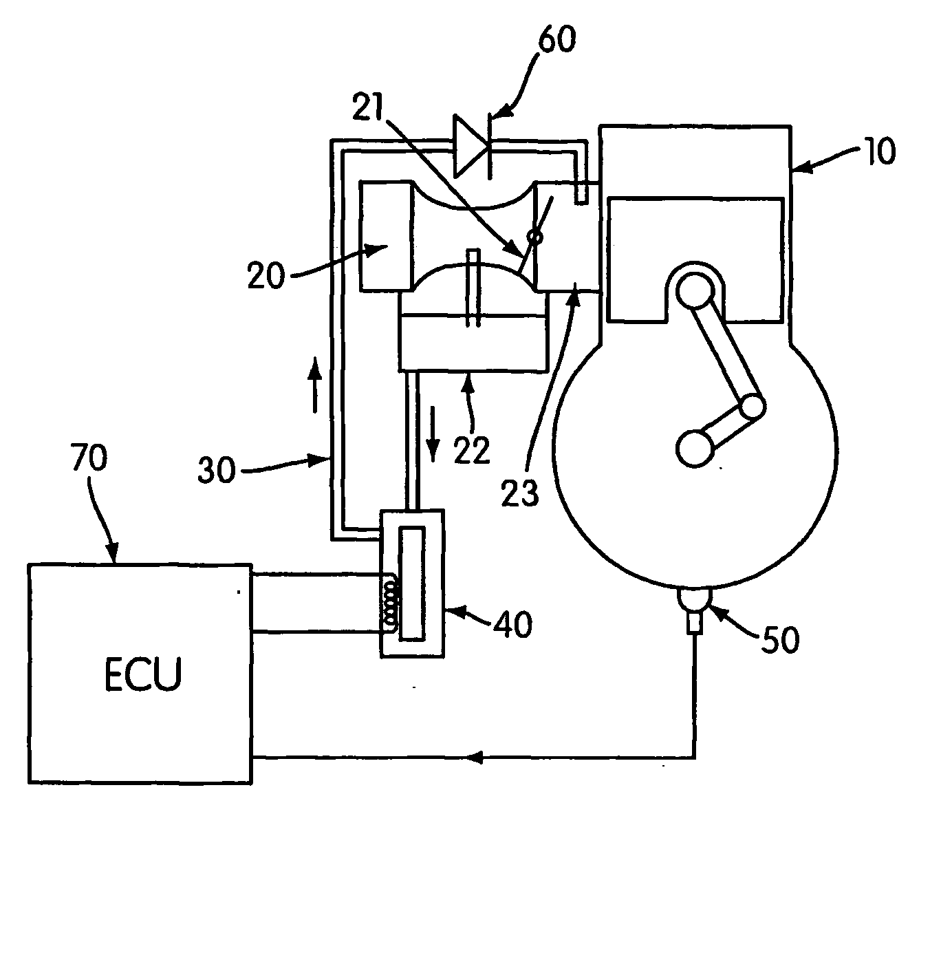
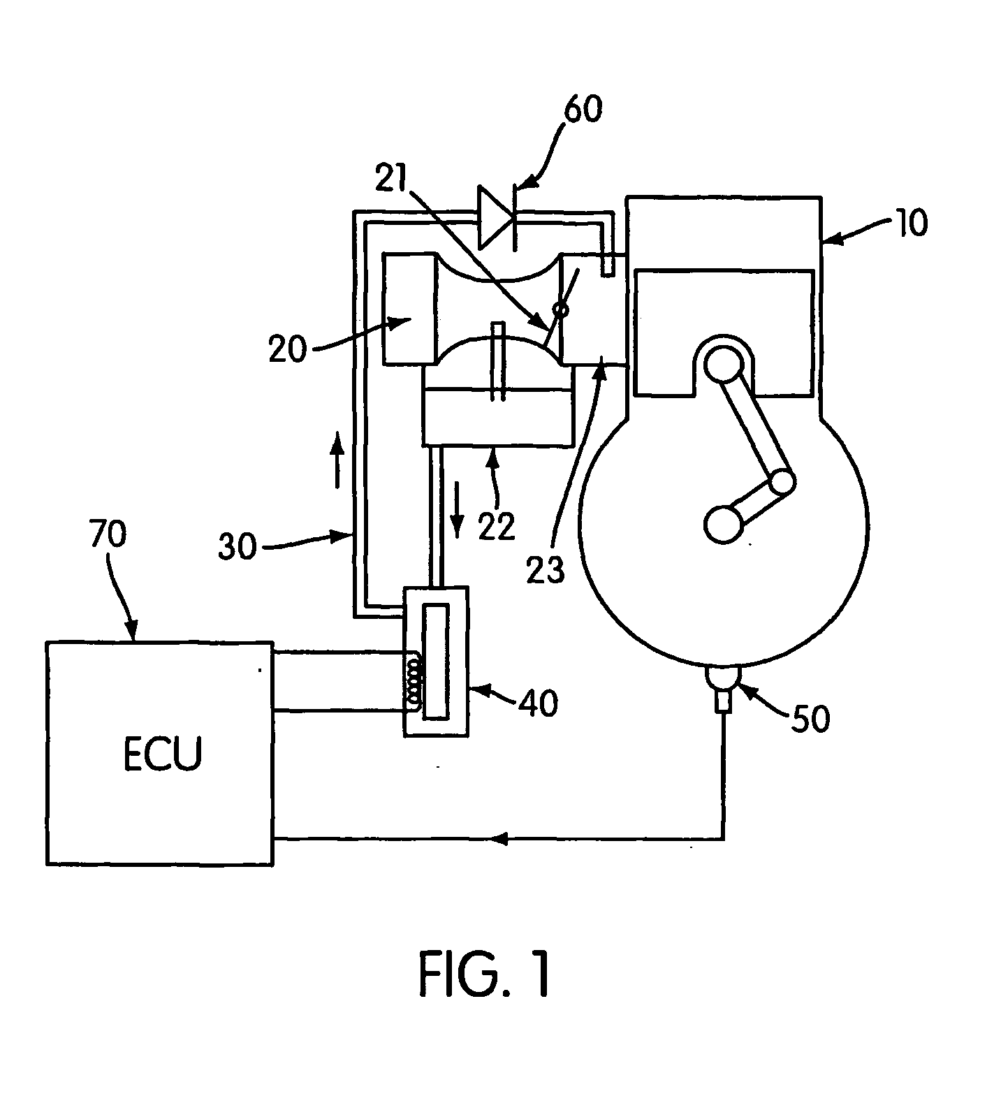
[0021] Referring to FIG. 1, an automatic carburetor enrichment system for an internal combustion engine 10 includes a carburetor 20 having a throttle valve 21. It should be appreciated that a carburetor having an air inlet of fixed size may also be used. The carburetor 20 also includes a float chamber 22 configured in the usual manner to ensure a constant fuel level within the chamber 22. It should be appreciated however that fuel may be supplied to the carburetor from a fuel reservoir separate from the carburetor. A fuel delivery line 30 extends from the float chamber 22 into the induction passage 23 of the carburetor 20. A solenoid valve 40 controls the flow of fuel from the float chamber 22 to the induction passage 23. A check valve 60 provides a balanced distribution of fuel to the cylinders of the engine 10 and prevents fuel from flowing back from the in...


PUM


Abstract

An automatic carburetor (20) enrichment system that controls the air-fuel mixture during cold start of an engine (10) having a carburetor including a fuel bowl (22) and an induction passage (23), includes a sensor (50) that provides a signal indicative of an engine temperature at engine start, a fuel line (30) connected between the fuel bowl (22) and the induction passage, a solenoid valve (40) disposed in the fuel line, and a controller (10) that receives the signal and sets a duty cycle of the solenoid valve associated with the engine temperature to increase the air-fuel ratio of the air-fuel mixture at engine start. The automatic carburetor enrichment system reduces cranking time during cold start, eliminates the need for driver input during cold start, prevents engine stalling without assistance from the operator during the warm up phase, provides a simpler, more cost effective and reliable carburetor enrichment, provides self-drowning protection without the use of an electronic idle switch and eliminates the risk of engine drowning when the engine is cranked with the choke ON and the ignition switches OFF.

Description

BACKGROUND OF THE INVENTION [0001] 1. Field of the Invention [0002] The present invention relates to systems and methods for automatic carburetor enrichment during cold start of an engine. [0003] 2. Description of the Related Art [0004] In internal combustion engines having carburetor controlled fuel supplies, for example, engines used in vehicles such as snowmobiles, personal watercraft, and all terrain vehicles, the rate of fuel flow in a fixed or variable venturi carburetor is dependent on the pressure differential between the venturi and the fuel bowl, also known as the float bowl or float chamber. In a conventional float bowl carburetor the pressure differential is measured between the pressure in the fluid float chamber, which is normally atmospheric, and the pressure at the discharge orifice of the fuel metering system which is normally located in or adjacent the venturi in the induction passage. [0005] For optimum combustion, the relationship between the mass air flow and th...

Claims


Application Information

Patent Timeline
IPC IPC(8): F02B61/00F02D41/06F02M1/04F02M1/10F02M5/00
CPCF02B61/00F02D41/064F02M5/00F02M1/10F02M1/04
Inventor RICHARD, KARLSCHUEHMACHER, BRUNO
Owner BOMBARDIER RECREATIONAL PROD INC
Learn More