
Image pickup system

a pickup system and image technology, applied in the field of image pickup system and image processing program, can solve the problems of inferior accuracy in estimating the noise amount, random noise generation in the image pickup elements and analog circuits, and deterioration of the edge portions

Active Publication Date: 2005-05-12
OLYMPUS CORP
View PDF10 Cites 64 Cited by
  • Summary
  • Abstract
  • Description
  • Claims
  • Application Information

AI Technical Summary

Benefits of technology

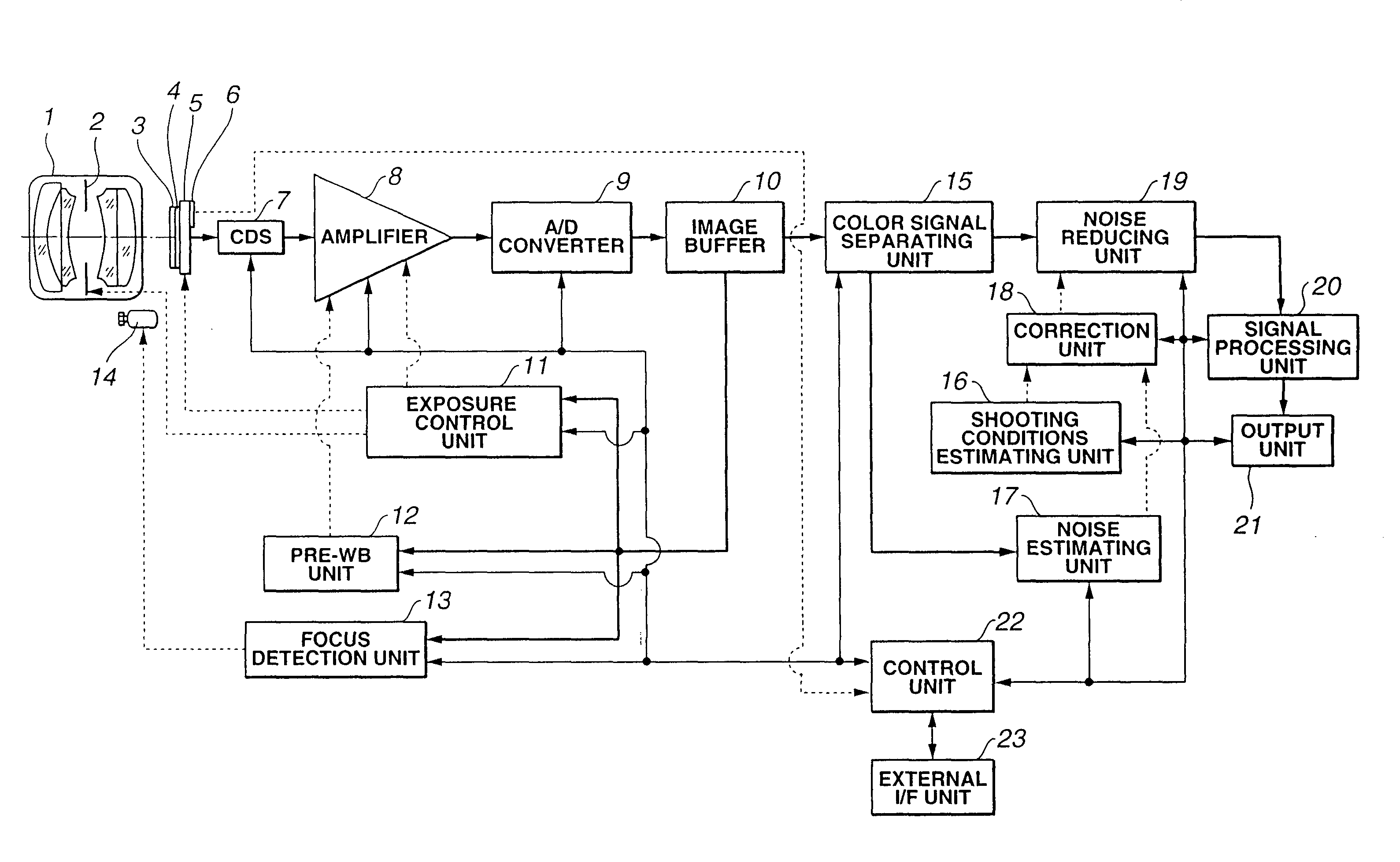
[0013] In short, the image pickup system comprises: a noise estimating unit which estimates the amount of noise contained in the digitized signal from an image pickup element in which a plurality of pixels are arranged, either for each pixel or for each specified unit area comprising a plurality of pixels; and a shooting situation estimating unit which estimates the shooting situation at the time that an image based on the abovementioned signal is shot. The amount of noise estimated by the abovementioned noise estimating unit is corrected on the basis of the shot situation estimated by the abovementioned shooting situation estimation unit, and the noise in the abovementioned signal is reduced on the basis of the corrected amount of noise.

Problems solved by technology

On the other hand, random noise is generated in the image pickup elements and analog circuits, and has characteristics that are close to white noise characteristics.
However, since the amount of noise varies dynamically according to factors such as the temperature at the time of shooting, exposure time, gain and the like, conversion to a function that matches the amount of noise during shooting cannot be handled in the case of a technique using static constant terms such as that described in the abovementioned Japanese Patent Application Laid-Open No. 2001-157057, so that the precision in estimating the amount of noise is inferior.
Furthermore, the filtering frequency characteristics are controlled from the amount of noise; however, since this filtering performs processing equally without discriminating between flat portions and edge portions, the edge portions deteriorate in regions where it is estimated on the basis of the signal level that the amount of noise is large.
Specifically, processing that discriminates between the original signal and noise cannot be handled, so that the preservation of the original signal is poor.
However, since this threshold value is also given as a static value, variation in the amount of noise according to the signal level cannot be handled, so that the selection of the average number of pixels or moving average method cannot be optimally controlled.
Consequently, noise components remain, and there is a deterioration of the original signal and the like.
However, in the abovementioned prior art, such points cannot be handled, so that there is a drawback that a subjectively ideal image may not always be obtainable even if noise reduction processing is performed.

Method used


Image

  • Image pickup system
  • Image pickup system
  • Image pickup system

Examples


first embodiment

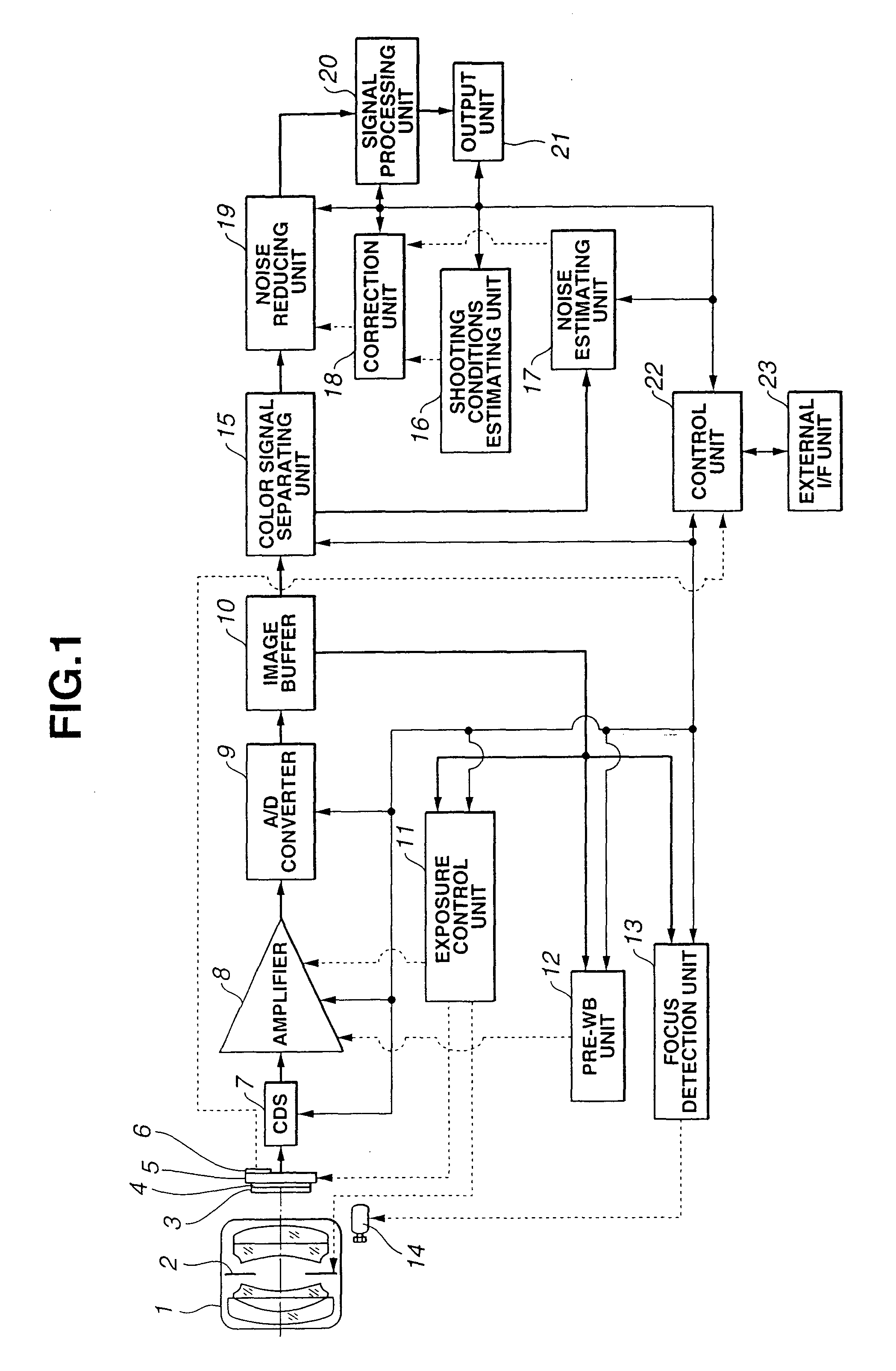
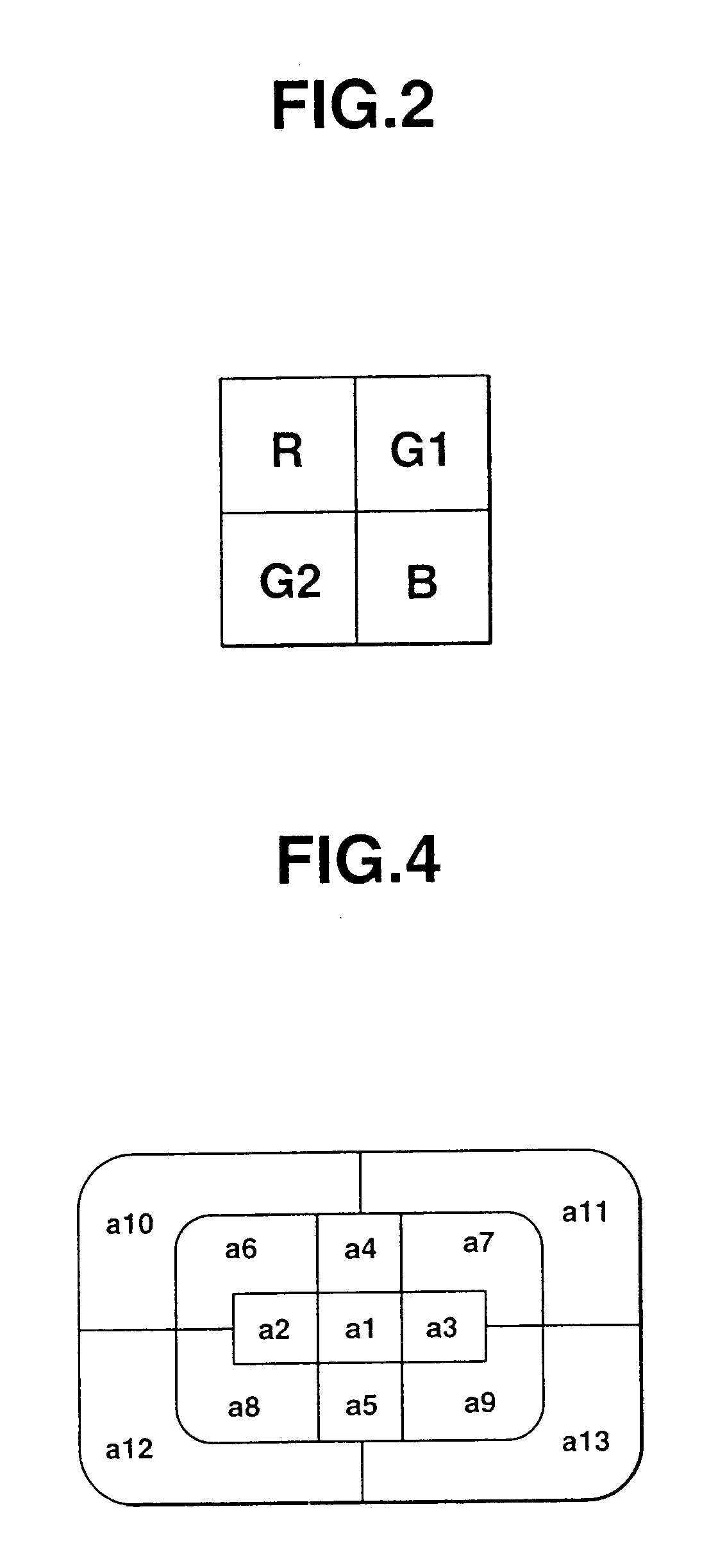
[0034]FIGS. 1 through 9 show the present invention. FIG. 1 is a block diagram which shows the construction of the image pickup system, FIG. 2 is a diagram which shows the primary color Bayer type filter construction in the color filters, FIG. 3 is a block diagram which shows the construction of the shooting situation estimating unit, FIG. 4 is a diagram which is used to illustrate the split pattern used for exposure controlling and the parameters used for evaluation, FIG. 5 is a block diagram which shows the construction of the noise estimating unit, FIGS. 6 and 7 are diagrams which are used to illustrate the formulization of the amount of noise, FIGS. 8A through 8D are diagrams which are used to illustrate the parameters used in the formulization of the amount of noise, and FIG. 9 is a block diagram which shows the construction of the noise estimating unit.

[0035] As is shown in FIG. 1, this image pickup system comprises: a lens system 1 which is used to form an image of the subject...

second embodiment

[0114]FIGS. 10 through 14 show the present invention. FIG. 10 is a block diagram which shows the construction of the image pickup system, FIGS. 11A and 11B are block diagrams which show examples of the construction of the shooting situation estimation unit, FIG. 12 is a block diagram which shows the construction of the noise estimating unit, FIG. 13 is a flow chart which shows a portion of the noise reduction processing that is performed by the image processing program in a computer, and FIG. 14 is a flow chart which shows a portion of the noise reduction processing that is performed by the image processing program in a computer.

[0115] In this second embodiment, parts that are the same as in the abovementioned first embodiment are labeled with the same symbols, and a description of such parts is omitted. For the most part, only points that are different will be described.

[0116] As is shown in FIG. 10, in addition to the construction of the abovementioned first embodiment, the image...


PUM


Abstract

An image pickup system has a noise estimating unit which estimates the amount of noise contained in a digitized signal from an image pickup element composed of an array of a plurality of pixels, either for each pixel or for each specified unit area made up of a plurality of pixels, and a shooting conditions estimation unit which estimates the shooting condition when an image based on the signal is acquired. The amount of noise estimated by the noise estimating unit is corrected on the basis of the shooting conditions estimated by the shooting conditions estimation unit, and the noise in the signal is reduced on the basis of the corrected amount of noise.

Description

CROSS-REFERENCE TO RELATED APPLICATION [0001] This application claims benefits of Japanese Application No. 2002-242400 filed in Japan on Aug. 22, 2002, the contents of which are incorporated by this reference. BACKGROUND OF THE INVENTION [0002] 1. Field of the Invention [0003] The present invention relates to an image pickup system and image processing program which reduce random noise arising in the image pickup element system. [0004] 2. Description of the Related Art [0005] Generally, noise components are contained in digitized signals obtained from image pickup elements and the associated analog circuits and A / D converters. Such noise components can be divided into two main categories, i. e., fixed pattern noise and random noise. [0006] The abovementioned fixed pattern noise, as typified by defective pixels or the like, is noise that originates mainly in the image pickup elements. [0007] On the other hand, random noise is generated in the image pickup elements and analog circuits...

Claims


Application Information

Patent Timeline
IPC IPC(8): H04N1/409G06T5/00H04N5/232H04N9/04H04N9/07
CPCH04N5/357H04N9/045H04N5/361H04N23/843H04N25/134H04N25/618H04N25/671H04N25/60H04N25/63
Inventor TSURUOKA, TAKAO
Owner OLYMPUS CORP
Learn More