

Light adjustable multifocal lenses
a multi-angle, adjustable technology, applied in the field of optical elements, can solve problems such as the expansion of the element in the area
- Summary
- Abstract
- Description
- Claims
- Application Information
AI Technical Summary
Benefits of technology
Problems solved by technology
Method used
Image

Examples
example 1
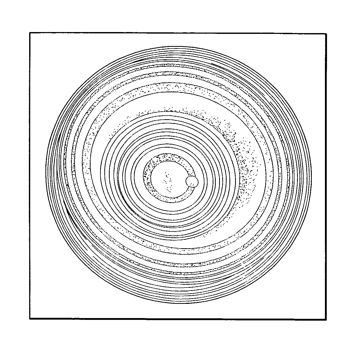
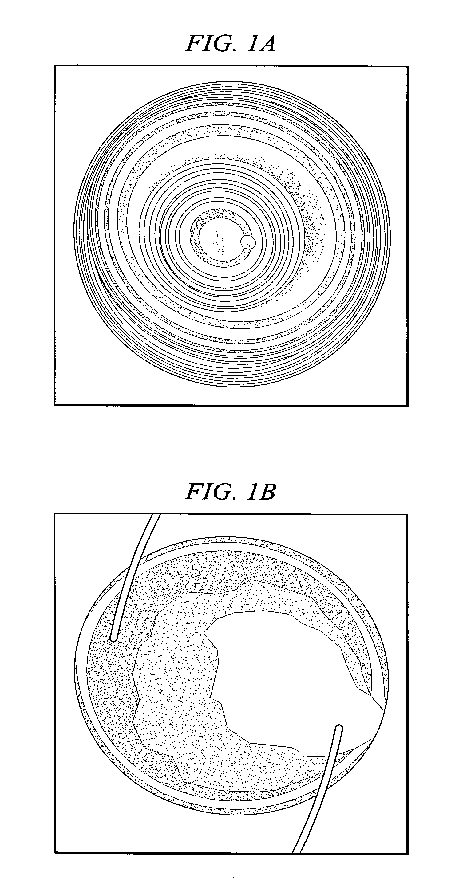
[0053] A 6 mm diameter intraocular lens containing a silicone-based MC was prepared using standard molding techniques known to those skilled in the art. The lens had a first polymer matrix prepared from a silicone hydride crosslinked vinyl endcapped diphenylsiloxane dimethylsiloxane. The first polymer matrix comprised about 70 weight % of the lens. The lens also comprised about 30 weight % of a MC (methacrylate endcapped polydimethylsiloxane), 1 weight % (based on MC) of a photoinitiator (benzoin-tetrasiloxane-benzoin), and 0.04 weight % (based on MC) UV absorber. The lens had an initial nominal power of 30 diopters. The center of the lens was then irradiated with 365 nm light using an intensity pattern represented by the equation: I=I0ⅇ-(r-rc)22σ2(1)
and an average intensity of 4.12 mW / cm2 for 60 seconds. Three hours post-exposure, the lens had a +3.25 D change over the central 2.5 mm region of the lens, which is shown in FIG. 1A. The interference fringes were taken at the preir...
example 2
[0058] One of the unique aspects of the above described technology is that we have the ability to first change the power of the IOL over the majority of its aperture and then reirradiate the lens over a small zone (0 to 3 mm) to create a bifocal lens as described in example 1. This embodiment has the advantages of first implanting the light adjustable lens in the patient, waiting the required healing time to let the eye refractively stabilize (typically two to four weeks), measuring the refraction of the patient to determine the necessary correction, if any, to bring the patient to emmetropia, irradiating the lens to change the power of the lens over the majority of the aperture, and then reirradiating a smaller zone in the lens (1.5-3 mm) along the patient's visual axis to provide the necessary multifocality for near and distance viewing.
[0059] As an example of this, a +20.0 D LAL was molded comprising 75 wt % of silicone matrix, 25 wt % of MC, 0.83 wt % PI, and 0.04 wt % UV absor...
example 3
[0061] In the past, the clinical use of bifocal or multifocal IOLs have met with some resistance by patients due to the loss of contrast sensitivity and glare that are inherent to this type of lens' designs. In the past, the only way for a physician to reverse the undesired affects of a previously implanted multifocal or bifocal IOL was to explant the IOL and reinsert it with a standard monofocal IOL. However, the light adjustable lens technology described in this disclosure and previous Calhoun Vision published works provides a means to reverse the multifocal properties of the LAL, effectively returning it to its monofocal condition. Such ability would have the oblivious advantage of reversal without surgical explantation.
[0062] As an example of this process, a +20.0 D LAL was molded comprising 75 wt % of silicone matrix, 25 wt % of MC, 0.83 wt % PI, and 0.04 wt % UV absorber. The preirradiation Fizeau interference fringes are shown in FIG. 4A. This LAL was then irradiated using t...
PUM
 Abstract
Description
Claims
Application Information