

Zoom lens and image-taking system
a zoom lens and image-taking technology, applied in the field of zoom lenses, can solve the problems of difficult control of the zoom function with a mechanical cam, increase the size of the zoom lens, and increase the size of the zoom lens, and achieve the effects of small movement amount of the focusing lens unit, favorable tracing performance and operability, and high zoom ratio and compactness
Image

Examples
example 1
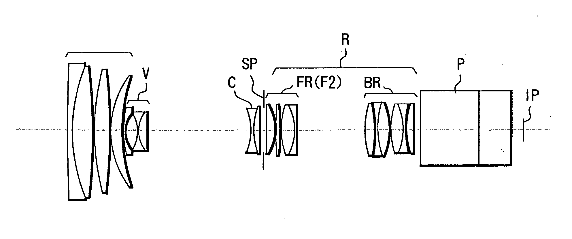
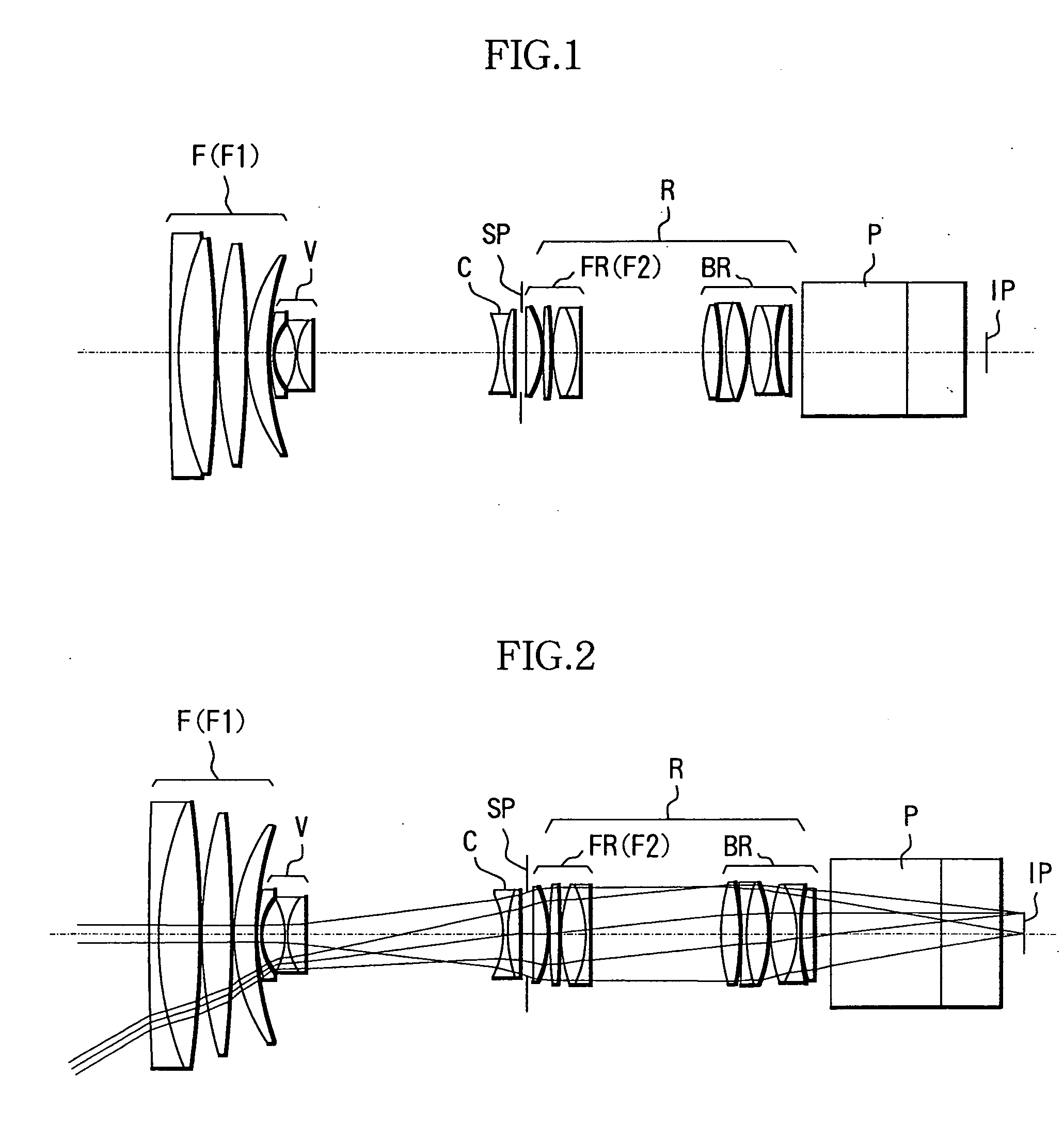
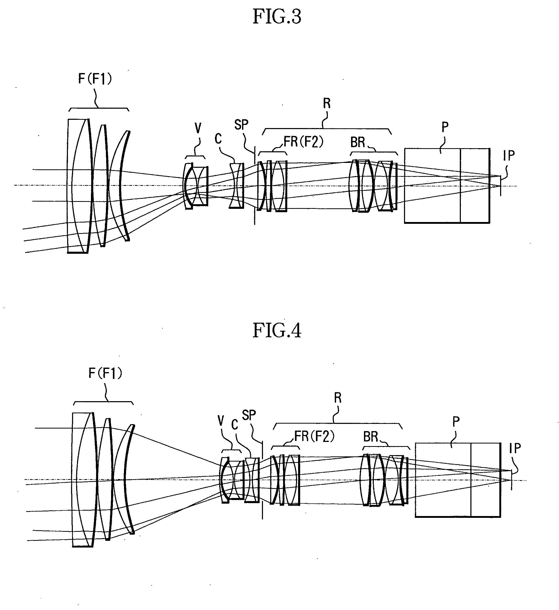
[0077]FIG. 1 shows a cross-sectional view of a zoom lens according to Example 1 of the present invention at the wide angle end at a magnification of 1×.
[0078] In FIG. 1, reference character F denotes a front lens unit as a first lens unit having positive refractive power. V denotes a variator lens unit for zooming as a second lens unit having negative refractive power which performs zooming from the wide angle end to the telephoto end by moving monotonously on the optical axis towards the image plane side. C denotes a compensator lens unit having negative refractive power which moves nonlinearly on the optical axis along a track which is convex toward the object side in order to compensate for shift of the image plane due to move of the variator lens unit V. The variator lens unit V and the compensator lens unit C together form a zooming system.
[0079] Reference character SP denotes a stop, and R denotes a fixed relay lens unit as a fourth lens unit having positive refractive power...
numerical example 1
[0090]
f = 10.30 fno = 1:2.05˜2.32 2ω = 56.2°˜4.2°r1 = 1169.481d1 = 2.40n1 = 1.81265ν1 = 25.4r2 = 98.429d2 = 10.83n2 = 1.51825ν2 = 64.2r3 = −265.170d3 = 0.20r4 = 124.037d4 = 8.29n3 = 1.60548ν3 = 60.7r5 = −281.395d5 = 0.20r6 = 51.797d6 = 6.46n4 = 1.64254ν4 = 60.1r7 = 97.915d7 = Variabler8 = 71.045d8 = 0.90n5 = 1.82017ν5 = 46.6r9 = 17.601d9 = 6.01r10 = −21.542d10 = 0.90n6 = 1.77621ν6 = 49.6r11 = 18.397d11 = 4.63n7 = 1.85501ν7 = 23.9r12 = −4295.134d12 = Variabler13 = −27.245d13 = 0.90n8 = 1.79013ν8 = 44.2r14 = 31.613d14 = 3.84n9 = 1.85501ν9 = 23.9r15 = 1125.345d15 = Variabler16 = 0.000 (Stop)d16 = 1.60r17 = 10000.000d17 = 4.60n10 = 1.66152ν10 = 50.9r18 = −28.234d18 = 0.20r19 = 224.718d19 = 2.53n11 = 1.48915ν11 = 70.2r20 = −178.770d20 = 0.20r21 = 40.193d21 = 6.76n12 = 1.48915ν12 = 70.2r22 = −30.275d22 = 1.20n13 = 1.83932ν13 = 37.2r23 = −1000.000d23 = 35.00r24 = 64.466d24 = 4.96n14 = 1.48915ν14 = 70.2r25 = −66.907d25 = 0.20r26 = −126.587d26 = 1.20n15 = 1.83932ν15 = 37.2r27 = 52.052d27 =...
example 2
[0092] A zoom lens according to Example 2 has the same configuration as Example 1, except that a focal-length changing optical system is inserted. FIG. 12 shows a cross-sectional view of a zoom lens according to Example 2 of the present invention at the wide angle end.
[0093] In FIG. 12, reference character IE denotes a focal-length changing optical system; The conversion magnification of the focal-length changing optical system IE of the present example is 2.0×.
[0094] Table 2 shows Numerical Example 2 of the present example. In Numerical Example 2, reference characters such as f, ri, di, ni and vi are the same as those described in Numerical Example 1.
[0095] FIGS. 13 to 17 are diagrams showing optical paths of the present example. FIG. 13 is a diagram showing an optical path in Numerical Example 2 when f is 20.60 mm and the object distance is 2.5 m; FIG. 14 is a diagram showing an optical path in Numerical Example 2 when f is 78.90 mm and the object distance is 2.5 m; FIG. 15 is ...
PUM
 Abstract
Description
Claims
Application Information
- IPC
- G02B15/10; G02B7/10; G02B15/167; G02B15/17
- CPC
- G02B15/17; G02B15/10; G02B15/144109
- Inventors
- NURISHI, RYUJI