

Hydrogen generation reactor chamber with reduced coking
a hydrogen generation and reactor chamber technology, applied in chemical/physical/physicochemical stationary reactors, catalyst activation/preparation, packaging, etc., can solve the problems of insufficient energy storage capacity of storage or rechargeable batteries, inability to provide compressed hydrogen, and inability to meet the needs of certain applications. , to achieve the effect of reducing carbon formation
- Summary
- Abstract
- Description
- Claims
- Application Information
AI Technical Summary
Benefits of technology
Problems solved by technology
Method used
Image

Examples
Embodiment Construction
[0031] According to one embodiment of the present invention, a method for preparing the metal substrate surface of a hydrogen generation reactor chamber to reduce carbon formation is provided.
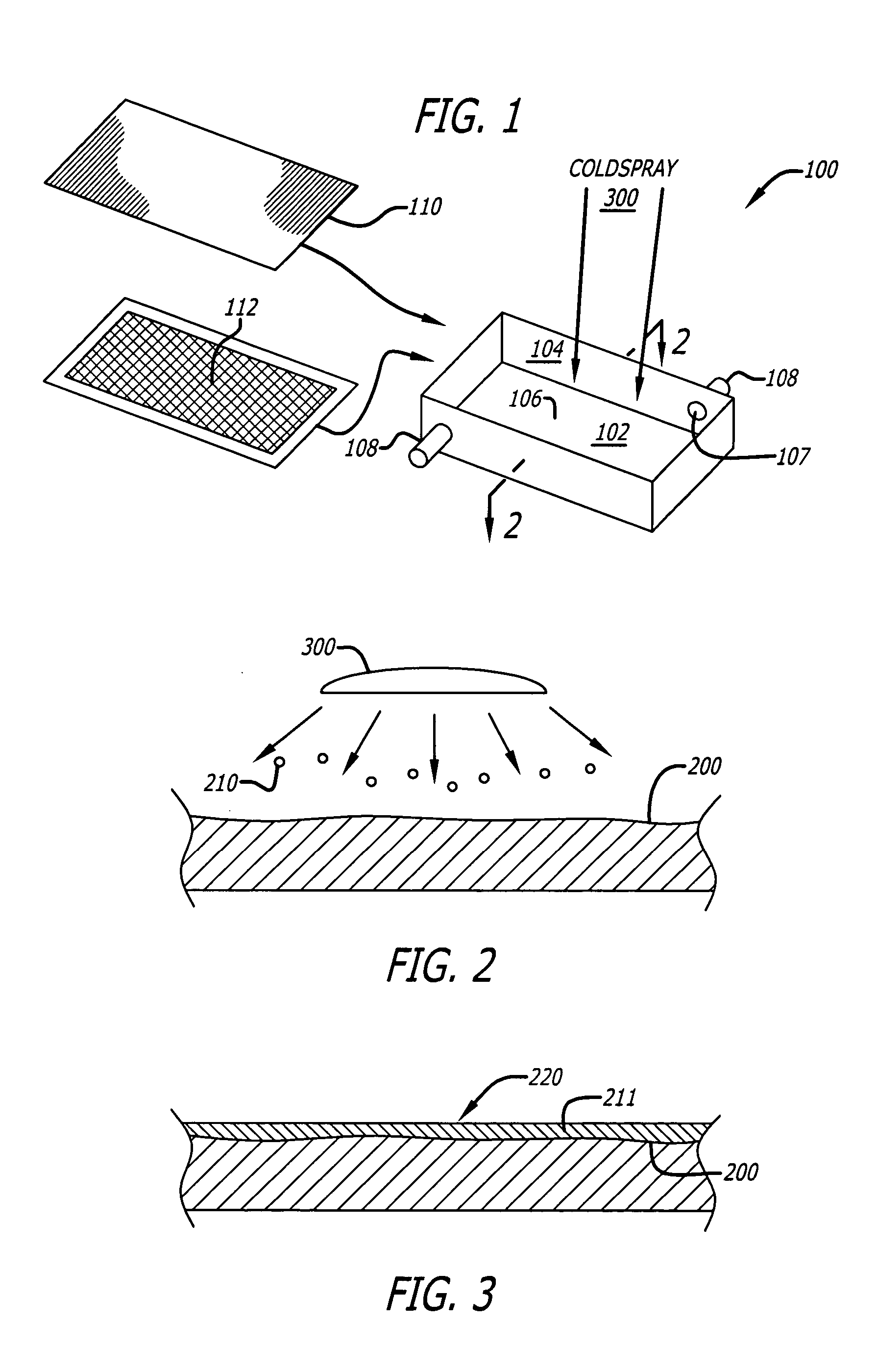
[0032] The present invention discloses a method of producing a hydrogen generation reactor chamber with reduced carbon formation on inner reactor surfaces.
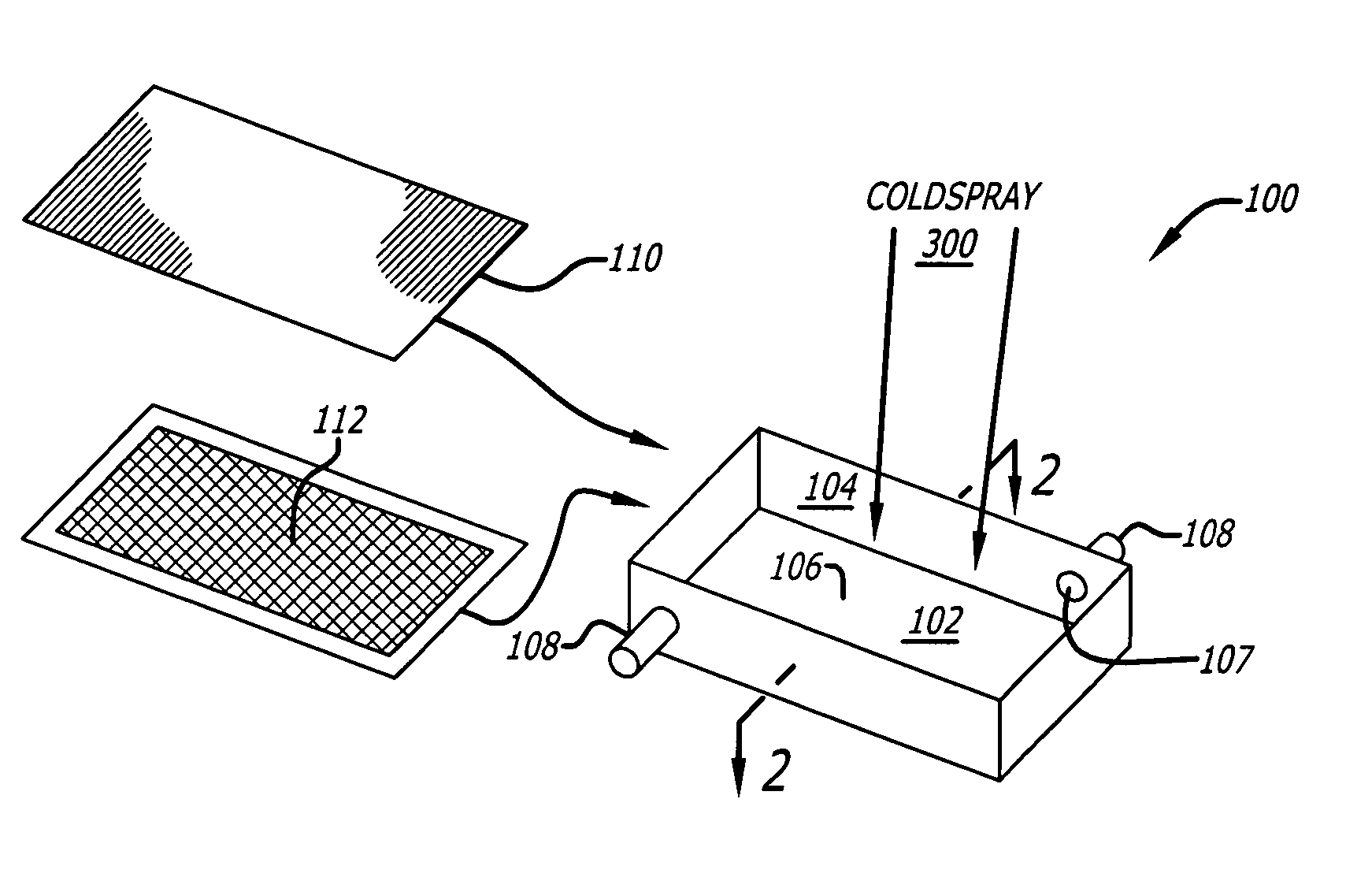
[0033] An exemplary reactor chamber 100 shown in FIG. 1 is a metal box with a floor 102, a side wall 104 surrounding the floor 102. While the exemplary reactor chamber shown has a rectangular shape, any hydrogen generation reactor chamber having useful geometry may be utilized, in accordance with the teachings of the present invention. For, example, cold spray may be applicable to coating large diameter tubular reactors. For diameters greater than 5 inches, there is no restriction in length of the tubing. For diameters <2 inches, length may be restricted to about 5 inches.
[0034] The focus of this invention is the inner surface 106 of the r...
PUM
| Property | Measurement | Unit |
|---|---|---|
| width | aaaaa | aaaaa |
| width | aaaaa | aaaaa |
| temperatures | aaaaa | aaaaa |
Abstract
Description
Claims
Application Information