Optical recording medium

a recording medium and optical recording technology, applied in the field of optical recording mediums, can solve the problems of limiting the output of a recording laser, the linear velocity of 10 m/s or above, and the insufficient sensitiveness of the recording layer, and achieves excellent light stability and favorable reflectance

Inactive Publication Date: 2005-05-12
TDK CORPARATION
View PDF18 Cites 46 Cited by
  • Summary
  • Abstract
  • Description
  • Claims
  • Application Information

AI Technical Summary

Benefits of technology

[0009] It is an object of the present invention to provide an optical recording medium that is capable of being recorded at a high linear velocity of at least 10 m / s while maintaining an excellent light stability and favorable reflectance.
[0011] According to the present optical recording medium, the recording layer is formed so as to include a second dye with an extinction coefficient of at least 0.5 at the recording wavelength. This makes it possible to provide an optical recording medium that can be recorded at a high linear velocity of at least 10 m / s while maintaining excellent light stability and favorable reflectance.

Problems solved by technology

Experiments conducted by the inventors of the present invention have confirmed that when recording is performed using a recording laser with a conventional output, the recording layer is not sufficiently sensitive, so that recording on an optical recording medium is problematic at a linear velocity of 10 m / s or above.
However, there are limits on the output of a recording laser, and in view of factors such as the durability of the laser, it is preferable for the output of the recording laser to be a predetermined level or below.
Accordingly, methods that raise the output of the recording laser to compensate for the insufficient sensitivity of the recording layer are not realistic.
On the other hand, with methods that make significant changes to the composition of the recording layer, it is difficult to maintain the electrical characteristics (excellent light stability and favorable reflectance) of the recording layer that is composed of the DVD-R dyes described above, and in many cases such changes cause problems, such as an increase in the error rate or a decrease in the reflectance.
Accordingly, one issue for current optical recording media is that it is difficult to perform recording at high speed while maintaining the excellent light stability and favorable reflectance.

Method used


Image

  • Optical recording medium
  • Optical recording medium
  • Optical recording medium

Examples


embodiments

[0030] The following describes the present invention in detail with reference to several representative embodiments.

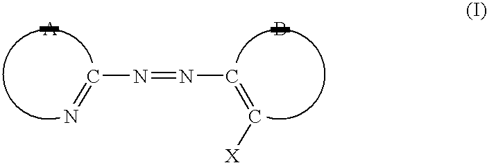
[0031] First the fundamental construction of the optical recording medium used in these embodiments will be described with reference to FIG. 2. The optical recording medium 10 is an optical recording medium that conforms to DVD-R Standard, and is constructed of a disc 20 that is recordable and a disc 30 (dummy substrate) that are bonded together by an adhesive 40. In this case, the disc 20 is composed of a substrate 21 in which grooves GR are formed (this substrate is normally formed of polycarbonate resin and is around 0.6 mm thick), and a recording layer 22, a reflective layer 23, and a protective layer 24 that are provided in order one on top of the other on top of the substrate 21. The disc 30 is composed of the same material as the substrate 21, for example. The adhesive 40 can be freely selected from materials such as a UV-hardening resin or a thermal-hardening ...

first embodiment

[0061] The metal azo dye shown by formula (VI) below was mixed with the pentamethine cyanine dye (with an extinction coefficient of 1.29 at a recording wavelength of 660 nm) shown by formula (III) above at a ratio by weight of 98:2 and after this the recording layer 22 was formed by application according to a spin-coating method and then drying. Also, an Ag reflective layer was formed by a sputtering method as the reflective layer 23. After this, the protective layer 24 was formed using the UV-hardening acrylic resin “DAICURE CLEAR SD318” (made by DAINIPPON INK AND CHEMICALS, INCORPORATED) as the material. The delayed-curing cation polymer adhesive “SK7000” (made by SONY CHEMICAL CORPORATION) was used as the adhesive 40.

second embodiment

[0062] The metal azo dye shown by formula (VI) above was mixed with the trimethine cyanine dye (with an extinction coefficient of 0.815 at a recording wavelength of 660 nm) shown by formula (IV) above at a ratio by weight of 97:3 and an optical recording medium was manufactured in the same way as the first embodiment.


PUM

PropertyMeasurementUnit
maximum absorption wavelengthaaaaaaaaaa
absorption wavelengthaaaaaaaaaa
wavelengthaaaaaaaaaa

Abstract

An optical recording medium can be recorded at a high linear velocity of at least 10 m / s while maintaining an excellent light stability and favorable reflectance. A recording medium is constructed of a recording layer on a substrate, the recording layer including a first dye with a maximum absorption wavelength in a thin-film state of 450 nm to 620 nm inclusive as a first dye and being formed so as to include a second dye with an extinction coefficient of at least 0.5 for a recording wavelength. In this case, it is preferable for the second dye to have a maximum absorption wavelength of 620 nm to 750 nm inclusive in a thin-film state.

Description

CROSS REFERENCE TO RELATED APPLICATION [0001] This application is a continuation of U.S. patent application Ser. No. 10 / 394,257, filed on Mar. 24, 2003, which claims priority of Japanese patent application No. 2002-085993 filed on Mar. 26, 2002, both of which are hereby incorporated herein in their entireties by reference.BACKGROUND OF THE INVENTION [0002] 1. Field of the Invention [0003] The present invention relates to an optical recording medium where dye is used in the recording layer, and in particular to an optical recording medium that can be recorded at high speed. [0004] 2. Description of the Related Art [0005] Large-capacity recordable optical discs (called DVD-R discs) have come onto the market as optical recording media that are capable of digital recording. DVD-R discs are constructed with a recording layer, a reflective layer, and a protective layer being successively formed on top of one another on a light-transmitting substrate, and have been standardized as media fo...

Claims


Application Information

Patent Timeline
Patent Type & Authority Applications(United States)
IPC IPC(8): B41M5/26G11B7/004G11B7/24035G11B7/244G11B7/2467G11B7/2472G11B7/249G11B7/2495G11B7/2542
CPCG11B7/2467Y10T428/21G11B7/2472G11B7/249G11B7/2492G11B7/2495G11B7/2533G11B7/2534G11B7/2536G11B7/2542G11B7/256G11B7/258G11B7/259G11B2007/24612G11B7/247
Inventor HORAI, TAKASHIARIOKA, HIROYUKIFUKUZAWA, NARUTOSHITSUKAMOTO, SYUJI
Owner TDK CORPARATION
Why Eureka
Try Eureka