
Sensor module

Active Publication Date: 2005-05-12
ROBERT BOSCH GMBH
View PDF4 Cites 49 Cited by
  • Summary
  • Abstract
  • Description
  • Claims
  • Application Information

AI Technical Summary

Benefits of technology

[0003] A sensor module according to an example embodiment of the present invention may have the advantage that it is usable with standard circuit board mounting techniques, while making proper shielding of the sensor system against electromagnetic interference possible. Advantageously, it may have a relatively simple design and may be manufacturable in a simple and cost-effective manner.
[0004] According to the present invention, a simple design having a high degree of shielding may be achieved in a surprisingly simple manner by connecting a conductive cover, which, according to the present invention, may basically have some non-conductive regions in addition to conductive regions, to a connector pin, so that the cover may be contacted directly via the connector pin together with the other connector pins when the components are mounted on the circuit board. The cover may thus be brought to a defined potential, preferably to ground potential.
[0005] According to a first example embodiment, a premolded housing having a lower housing part and a cover may be used. The conductive cover is advantageously inserted into the lower housing part. According to an alternative second example embodiment, the lead frame and the sensor system may be encapsulated, a die pad connected to ground being able to be co-encapsulated underneath the sensor system to improve the shielding effect. One or more active or passive components, i.e., chips, may be accommodated in the housing.
[0011] According to an example embodiment of the present invention, a plurality of ground pins bent toward the cover may also form a grid of leads for reducing the lateral EMC radiation.

Problems solved by technology

In both systems, electromagnetic compatibility (EMC) is in general difficult to achieve via adequate shielding.
This is a problem, for example, when using capacitively read sensors, for example micromechanically structured acceleration sensors and rotational speed sensors.
EMC capacitors, an optimized printed conductor layout, external shields in the housing, or robust analyzer circuits and circuit principles may be used here; however, even using these measures, the demands for EMC in safety-critical applications, in the automobile industry in particular, are often not met, so that considerable optimizing efforts are needed for using the sensors in such safety-critical applications.

Method used


Image

  • Sensor module
  • Sensor module
  • Sensor module

Examples


Embodiment Construction

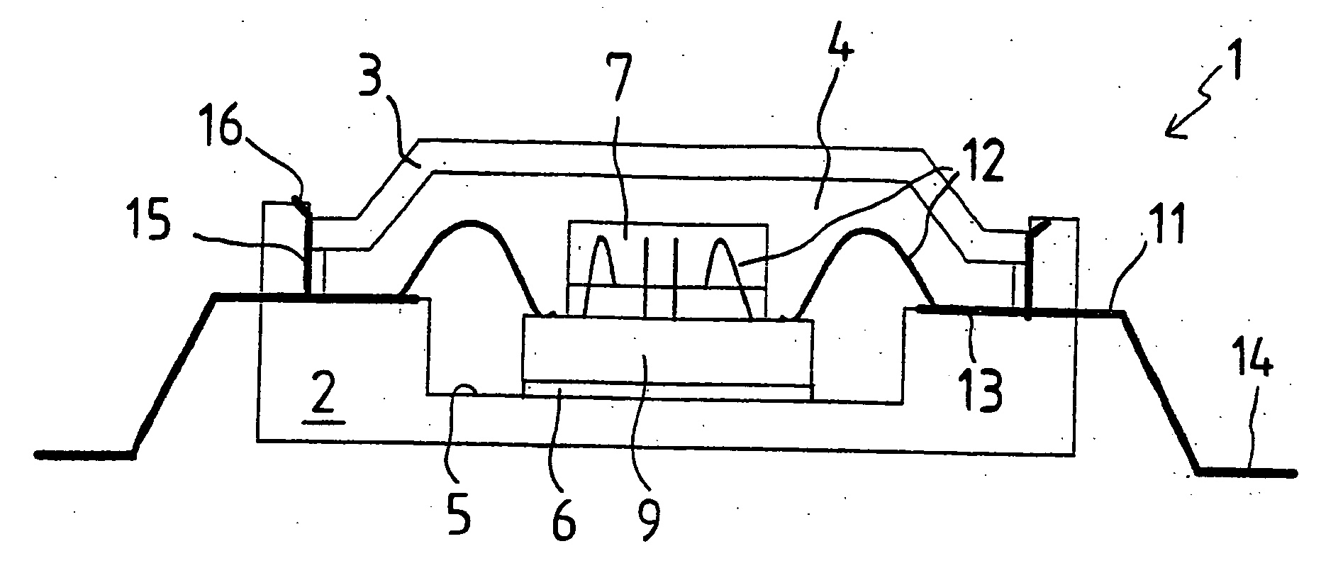
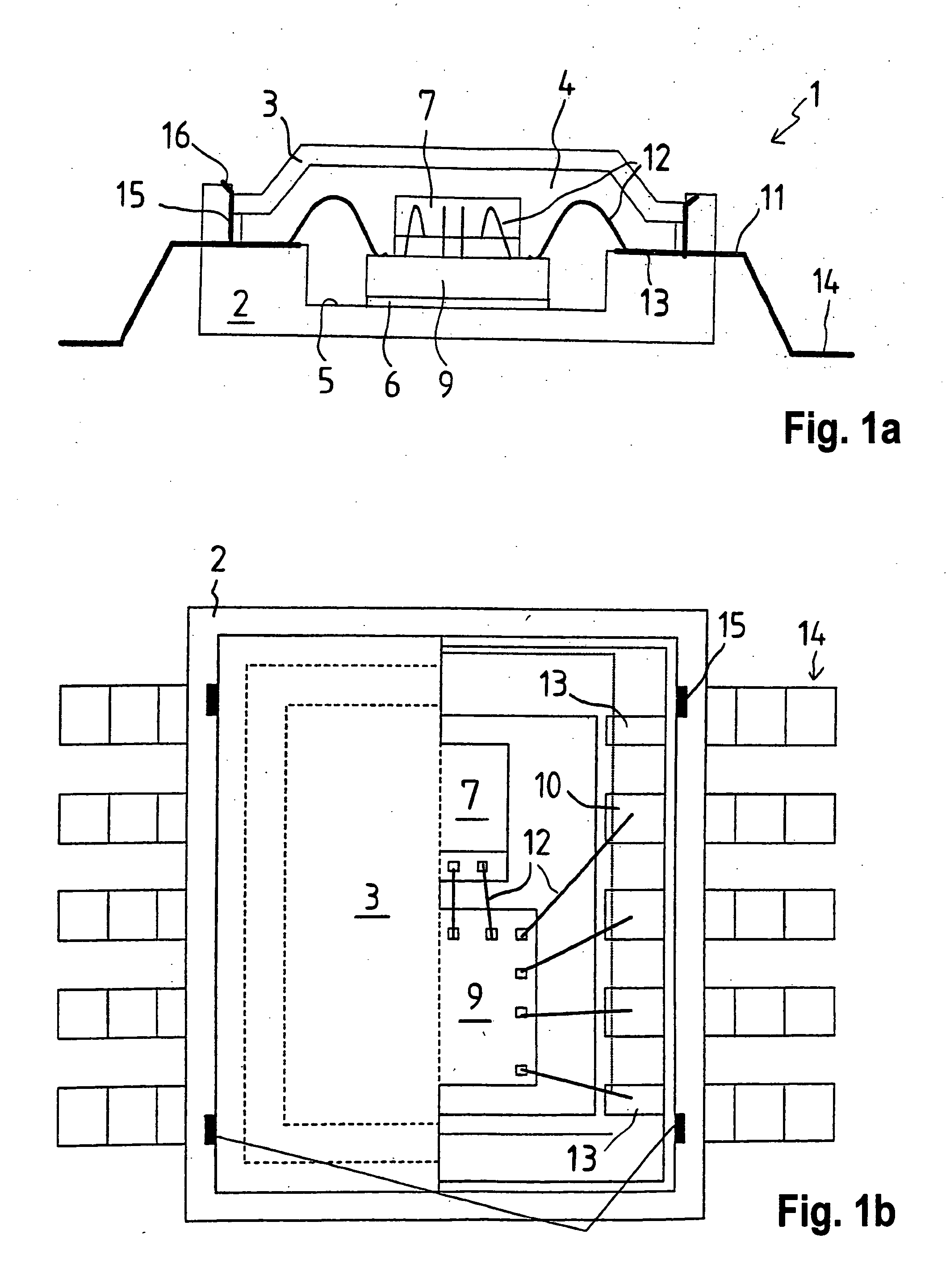
[0030]FIGS. 1a, b show a sensor module 1 has a premolded housing 2, 3 having a lower housing part 2 made of plastic and a metallic cover 3, between which an internal space 4 is formed. A sensor chip 7 and an analyzer chip 9, for example an ASIC (application-specific integrated circuit), are glued in interior space 4 on an internal surface 6 of lower housing part 2 using adhesive layers 6; the sensor chip and the analyzer chip are connected to one another and to contact regions of leads 10, 13 of a lead frame 11 via conductor bonds 12 in an essentially known manner. Lead frame 11 extends through lower housing part 2 and has ground leads 13 and further leads 10, whose outer ends transition into connector pins 14 protruding downward for attachment to a circuit board, which is not shown.

[0031] Sensor chip 7 may be in particular a microstructured component, for example, an acceleration sensor having vertical plates, which are deformed, according to their elasticity, under the effect of ...


PUM


Abstract

A sensor module, in particular for measuring an acceleration or rotational speed, having a housing base body made of a plastic material, a lead frame extending through the housing base body and having leads which have connector pins for attachment to a circuit board, a sensor system having at least one sensor chip, the sensor system being in contact with the lead frame via conductor bonds, a cover, which is connected to the base body and at least one connector pin and is made of a conductive material. A simple construction having a high shielding effect is achieved due to the fact that the conductive cover is connected to the connector pin. The cover, a lid, for example, may be contacted directly via the connector pin together with the other connector pins when the components are mounted on the circuit board. The sensor module may be molded or may have a premolded housing. The edge or a contact of the cover may be welded, soldered, glued, or pressed to a ground lead of the lead frame.

Description

FIELD OF THE INVENTION [0001] The present invention relates to a sensor module for measuring an acceleration or a rotational speed, in particular in conjunction with sensors sensitive to electromagnetic radiation. BACKGROUND INFORMATION [0002] Sensor modules to be mounted on a circuit board have, in general, a plastic housing and connector pins for contacting on the circuit board. The sensor chip or a sensor chip and an analyzer chip are either mounted on a lead frame and encapsulated in plastic or inserted into a premolded housing having an integrated lead frame which is sealed by a cover. In both systems, electromagnetic compatibility (EMC) is in general difficult to achieve via adequate shielding. This is a problem, for example, when using capacitively read sensors, for example micromechanically structured acceleration sensors and rotational speed sensors. EMC capacitors, an optimized printed conductor layout, external shields in the housing, or robust analyzer circuits and circu...

Claims


Application Information

Patent Timeline
IPC IPC(8): H01L27/14B81B7/00G01P1/02H01L23/02H01L31/14H01R13/658
CPCB81B7/0064H01R13/6594B81B2201/0242G01P1/023H01L2224/48091H01L2224/48247H01L2224/48472H01L2224/73265B81B2201/0235H01L2224/48137H01L2924/3025H01L2224/32225H01L2924/01068H01L2924/00014H01L2924/00H01L27/14H01L31/14H01L23/02
Inventor WEIBLEN, KURTSCHMICH, FRANZEMMERICH, HARALDOFFTERDINGER, KLAUSBEUTEL, HANSJOERGWEHRMANN, JOHANNGRABMAIER, FLORIAN
Owner ROBERT BOSCH GMBH
Features
  • Generate Ideas
  • Intellectual Property
  • Life Sciences
  • Materials
  • Tech Scout
  • Unparalleled Data Quality
  • Higher Quality Content
  • 60% Fewer Hallucinations
Learn More