
Indwelling urinary catheter

a catheter and bladder technology, applied in the field of surgical devices, can solve the problems of kidney obstruction, small child's inability to urinate, renal failure, etc., and achieve the effect of sufficient stiffness

Active Publication Date: 2005-05-12
LOTUS MEDICAL TECH
View PDF35 Cites 60 Cited by
  • Summary
  • Abstract
  • Description
  • Claims
  • Application Information

AI Technical Summary

Benefits of technology

[0022] It is a further object of the this invention to provide a hollow elastomeric tube that can have sufficient stiffness to be inserted into the bladder through the urethra without the need for a stylet.
[0023] It is an important object of the this invention to provide a hollow elastomeric tube that has means for being retained within a urinary bladder which minimize the contact area of the catheter with the bladder wall and permit complete drainage of the bladder without obstructing the outflow of urine.
[0024] It is a further object of this invention that when positioned within the bladder, the tip of the indwelling urinary drainage catheter can be reversibly opened by means that deform the catheter tip into a retaining mushroom shape in non-continuous contact with the bladder wall, and furthermore, permits all the urine to drain from the bladder.

Problems solved by technology

For example, a small child may not be able to urinate because of some congenital abnormality that obstructs the bladder neck or urethra.
If the bladder is not adequately drained the pressure in the bladder increases and the pressure likewise increases in the ureters and kidneys, causing the kidneys to become obstructed.
Unrelieved bilateral kidney obstruction may lead to renal failure within a few weeks.
There are some serious drawbacks to the standard indwelling urinary catheters now available.
This weight often causes pain and bladder irritation, generally known among urologists to provoke very painful bladder spasms.
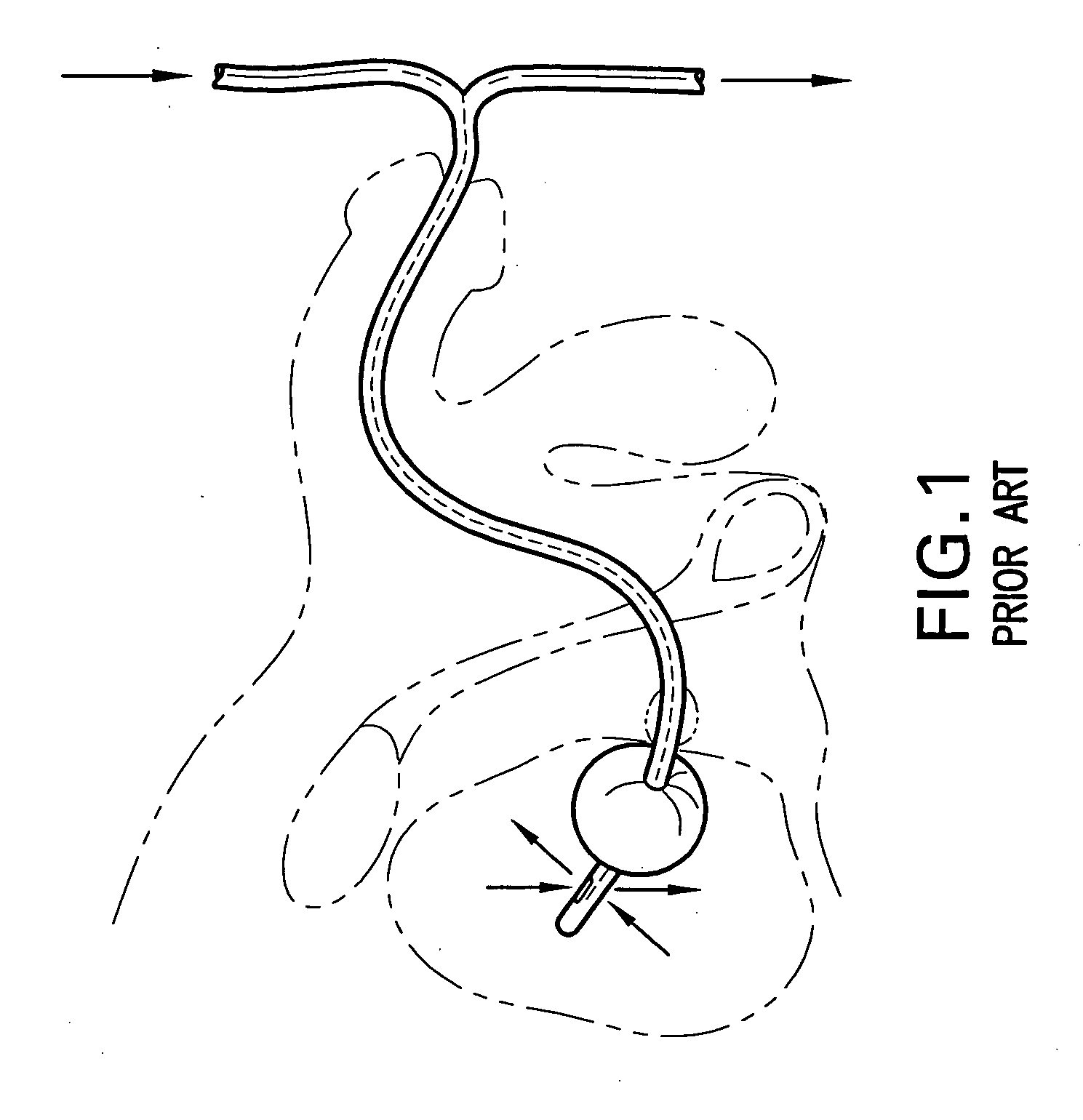
In addition to its weight, the balloon is situated below the drainage opening of the Foley catheter, so residual urine inevitably collects in the bladder around the balloon.
The presence of residual urine promotes infection and is a further source of bladder irritation.
Furthermore, in rare instances, the balloon may be inadvertently inflated inside of the urethra, causing trauma to the urethra and resulting thereby in pain, bleeding and possible stricture formation within the urethra.
The use of a stylet to introduce the catheter into the urinary tract and bladder is dangerous and potentially traumatizing.
The urethra is S-shaped when the penis is flaccid and becomes L-shaped when the penis is stretched or when erect; using a straight wire stylet thus could perforate the urethral wall, a most serious complication.
Furthermore, catheters are usually inserted by nurses but prevailing standards of care and insurance constraints do not allow nurses to use a stylet to insert a urinary drainage catheter because of the associated risks of urethral trauma and / or perforation.
It is not practicable to have a urinary catheter system that relies on a stylet for placement since nurses, who are the healthcare providers most widely relied on for catheter insertions, are not permitted to use them.
The structure of this system is complex and very expensive to manufacture.
The use of a tube-within-a-tube system compromises the drainage catheter lumen and obstructs the drainage of urine.
The urinary drainage system of this reference is both complex and expensive to manufacture.
Despite some similarities to the present subject Patent system, this reference system is a drainage tube with a sliding mechanism of action, designed to be inserted surgically, and inappropriate for transurethral placement.

Method used


Image

  • Indwelling urinary catheter
  • Indwelling urinary catheter
  • Indwelling urinary catheter

Examples


Embodiment Construction

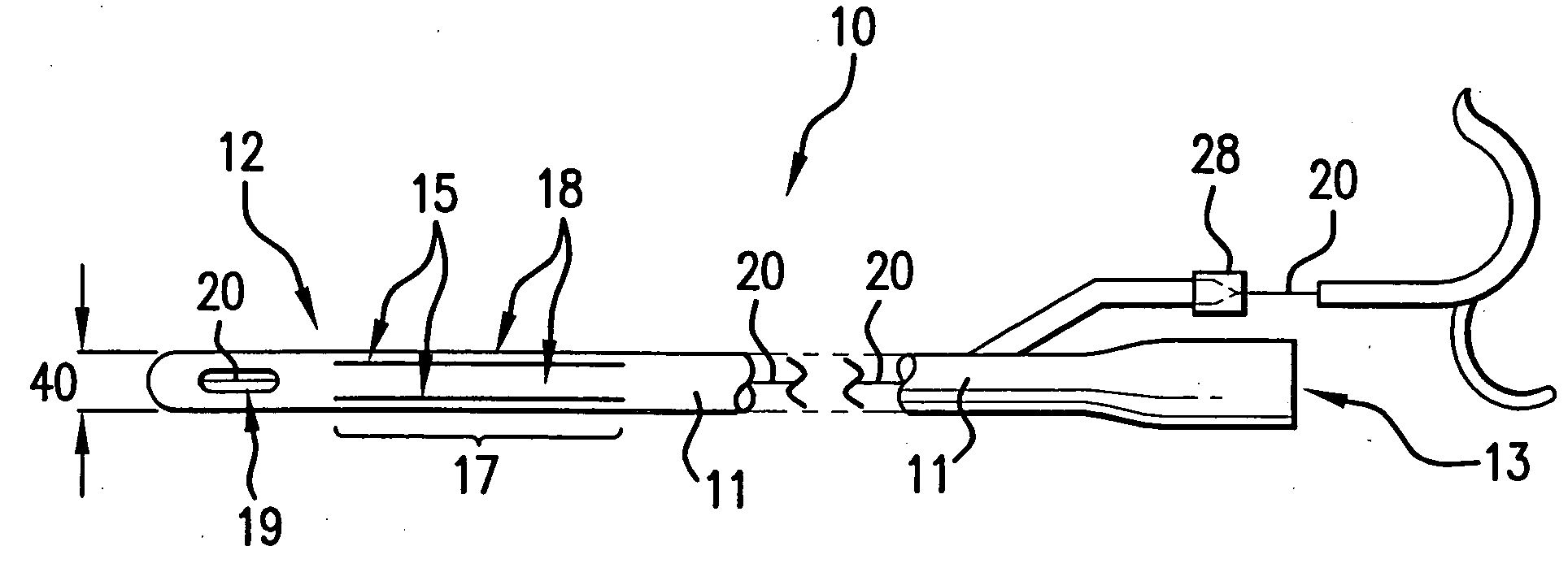
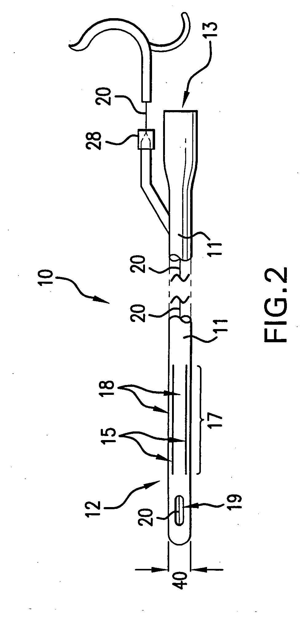
[0031] Referring now to the drawings, a urinary drainage catheter of the prior art is seen in FIG. 1, illustrating a typical Foley catheter. The retaining balloon when inflated, abuts in a continuous manner against the inner bladder wall; its drainage opening is proximal to the retaining balloon and thus allows there to be residual urine pooling at the base of the bladder. The present invention provides for non-continuous contact of the retention means with the bladder, thereby reducing the area of bladder-atheter contact and the resulting bladder wall irritation. The present subject invention further provides for drainage apertures distal to the retention means thereby facilitating complete urinary drainage, that is, eliminating any residual urine and thus further reducing bladder wall irritation. Furthermore, the catheter of the present invention can be inserted into and removed from a patient without using a stylet. In addition, the catheter components for reversably activating t...


PUM


Abstract

The retention balloon of the Foley urinary drainage catheter is replaced by a new self-retaining system. This new self-retaining catheter eliminates the problem of residual urine and also of bladder wall irritation caused by continuous contact with a spherical retention balloon; it also does not rely on a stylet for placement. The new system may use an internal control wire that reversibly foreshortens the proximal end of the catheter thus radially displacing longitudinal strips defined in the proximal catheter to form retention wings. Alternatively, a balloon situated between the longitudinal strips is inflated to force open the retention wings once inside the urinary bladder. Radial displacement of the retention wings widens the spaces between the longitudinal strips, these spaces constituting the drainage apertures which permit complete emptying of the urinary bladder, thereby eliminating a source of bladder irritation. The radially displaced retention wings abut the bladder wall in a non-continuous manner thereby reducing the area of bladder-catheter contact and further reducing bladder wall irritation.

Description

BACKGROUND OF THE INVENTION [0001] 1. Field of the Invention [0002] This invention relates generally to the field of surgical devices, and, more particularly, to an indwelling catheter for draining the urinary bladder, with the proximal part of the catheter being self-retaining in a manner that minimizes bladder irritation and leaves essentially no residual urine in the bladder. [0003] 2. Prior Art [0004] A urinary bladder drainage tube is used in certain patients who have had major surgery and / or trauma, or in any patient unable to urinate. There are many causes of an inability to urinate, these causes differing with age and sex. For example, a small child may not be able to urinate because of some congenital abnormality that obstructs the bladder neck or urethra. In females, inability to urinate occurs in neurological diseases, or after major abdominal or pelvic surgery. [0005] It is often desirable to drain the bladder continuously after major surgery or trauma, at least for the ...

Claims


Application Information

Patent Timeline
IPC IPC(8): A61M25/00A61M25/04A61M27/00
CPCA61M25/04A61M25/0017
Inventor HAKKY, SAID I.HAKKI, A-HAMID
Owner LOTUS MEDICAL TECH
Learn More