Signal transmission structure

a transmission structure and signal technology, applied in the direction of waveguides, waveguide type devices, high frequency circuit adaptations, etc., can solve the problems of incompletion of the transmission of signals from one end to the other of the signal line, inability to substantially improve and still inability to efficiently reduce the effective permittivity of the plating bar and enhance the resonant frequency thereof. , to achieve the effect of improving the transmission quality of high frequency signals and reducing

Active Publication Date: 2005-05-19
VIA TECH INC
View PDF1 Cites 11 Cited by
  • Summary
  • Abstract
  • Description
  • Claims
  • Application Information

AI Technical Summary

Benefits of technology

[0011] Therefore, the present invention provides a signal transmission structure adapted to reduce impendence mismatch of the signal line resulting from the plating bar in order to improve the transmission quality of the signals.

Problems solved by technology

Because of the impedance mismatch of the signal line 110 resulting from the plating bar 120, a big insertion loss or a small return loss occurs which results in the incompletion of the transmission of signals from one end to the other of the signal line 110.
Although the issue can be resolved by the approach, it still cannot efficiently reduce the effective permittivity of the plating bar and enhance the resonant frequency thereof for the high frequency or speed signal transmission structures.
Therefore, under this circumstance, the transmission quality of high frequency signals cannot be substantially improved.

Method used


Image

  • Signal transmission structure
  • Signal transmission structure
  • Signal transmission structure

Examples


Embodiment Construction

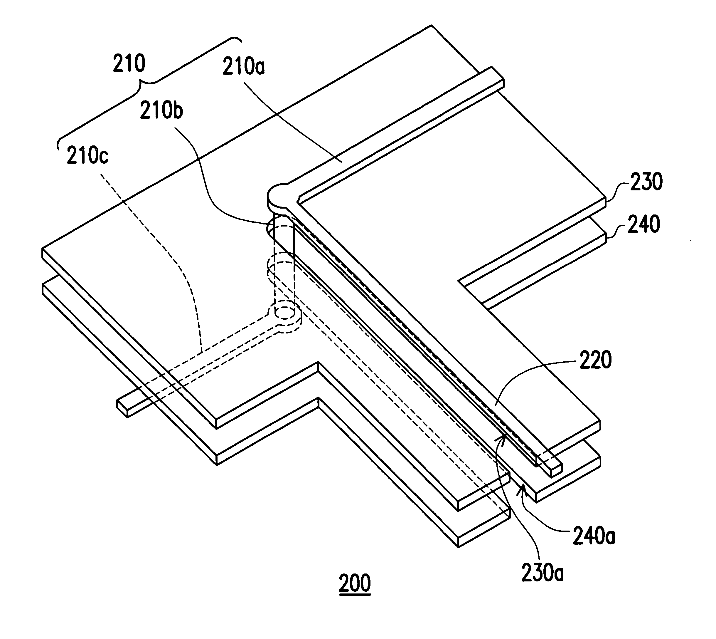
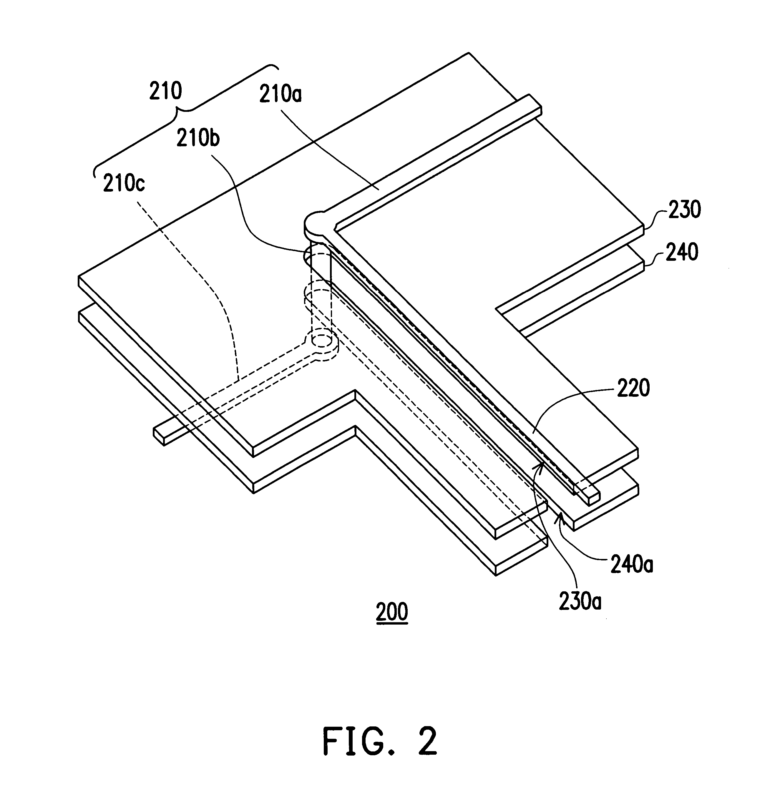
[0022]FIG. 2 is a schematic stereo configuration showing a signal transmission structure according to a preferred embodiment of the present invention. The signal transmission structure 200 is adapted for a multilayer patterned circuit substrate, such as a four-layer patterned circuit substrate. The signal transmission structure 200 comprises a signal line 210, a plating bar 220, a ground plane 230 and a power plane 240. The ground plane 230 is disposed over the power plane 240 and parallel thereto. The signal line 210 is composed of a first signal line 210a, a via 210b and a second signal line 210c. The first signal line 210a is disposed on the ground plane 230, and the second signal line 210c is disposed under the power plane 240. The first signal line 210a, the ground plane 230, the power plane 240 and the second signal line 210c can be sequentially formed on each layer of the four-layer patterned circuit substrate. In addition, the via 210b, through the ground plane 230 and the p...


PUM


Abstract

A signal transmission structure is disclosed. The signal transmission structure is adapted for a circuit substrate, including at least a signal line, a plating bar and a reference plane. The plating bar is disposed on a side of the reference plane and connected to the signal line. In addition, the plating bar is disposed on the side of the reference plane, and the reference plane has a non-reference area corresponding to the plating bar. The signal transmission structure can reduce the impedance mismatch at the conjunction of the signal line and the plating bar, and the resonant frequency of the plating bar can be improved as to generate a desired transmission quality of the signal.

Description

CROSS-REFERENCE TO RELATED APPLICATION [0001] This application claims the priority benefit of Taiwan application Ser. No. 92131758, filed Nov. 13, 2003. BACKGROUND OF THE INVENTION [0002] 1. Field of the Invention [0003] The present invention relates to a signal transmission structure, and more particularly to a signal transmission structure adapted to reduce impedance mismatch on signal lines resulting from the plating bar and to enhance the resonant frequency thereof. [0004] 2. Description of the Related Art [0005] In circuit substrates, signal lines applied thereon to couple two ports or components and used for transmitting signals, especially high frequency or speed, signals should be kept at a constant width for maintaining characteristic impedance thereof. Moreover, the impedance mismatch of the signal lines for transmitting the signals should be improved to reduce the reflection of signals stemming therefrom. Therefore, to reduce the insertion loss of the signal transmission ...

Claims


Application Information

Patent Timeline
Patent Type & Authority Applications(United States)
IPC IPC(8): H01P1/04H01P3/08H05K1/02H05K3/24
CPCH01P1/047H01P3/08H05K2201/0969H05K3/242H05K2201/093H05K1/0253
Inventor LEE, SHENG-YUAN
Owner VIA TECH INC
Why Eureka
Try Eureka