Tunable filter membrane structures and methods of making

Inactive Publication Date: 2005-05-19
AEGIS SEMICON
View PDF2 Cites 38 Cited by
  • Summary
  • Abstract
  • Description
  • Claims
  • Application Information

AI Technical Summary

Benefits of technology

[0008] Other embodiments include one or more of the following features. The multilayered thin film structure is fabricated on the top surface of the substrate. The multilayered thin film structure further includes a heater layer for heating the thermally tunable optical filter structure. The optical device also includes a heater element for heating the thermally tunable optical filter structure. The heater element is formed on the multilayered thin film structure. The thermally tunable optical filter structure is a thermo-optically tunable thin film optical filter structure. The heater element is a trace of resistive material that circumscribes a central region that is located over the hole. The trace of resistive material is a ring-shaped trace of resistive material. The thin film optical filter structure spans the opening. The thin film optical filter structure includes one or more layers comprising amorphous semiconductor, e.g. amorphous silicon. The multilayered thin film structure further includes a layer of silicon supporting the optical filter structure

Problems solved by technology

These devices, which are made from amorphous semiconductor materials, exploit what had previously bee

Method used


Image

  • Tunable filter membrane structures and methods of making
  • Tunable filter membrane structures and methods of making
  • Tunable filter membrane structures and methods of making

Examples


Embodiment Construction

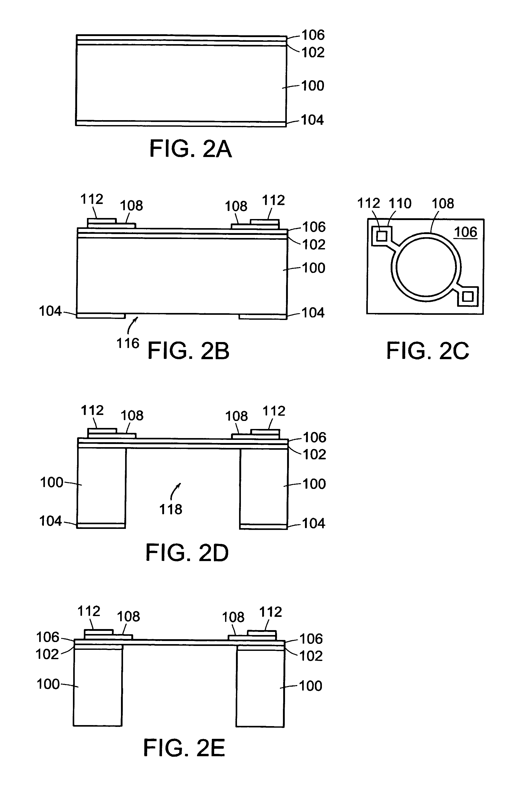
[0024] Simple Membrane Structure:

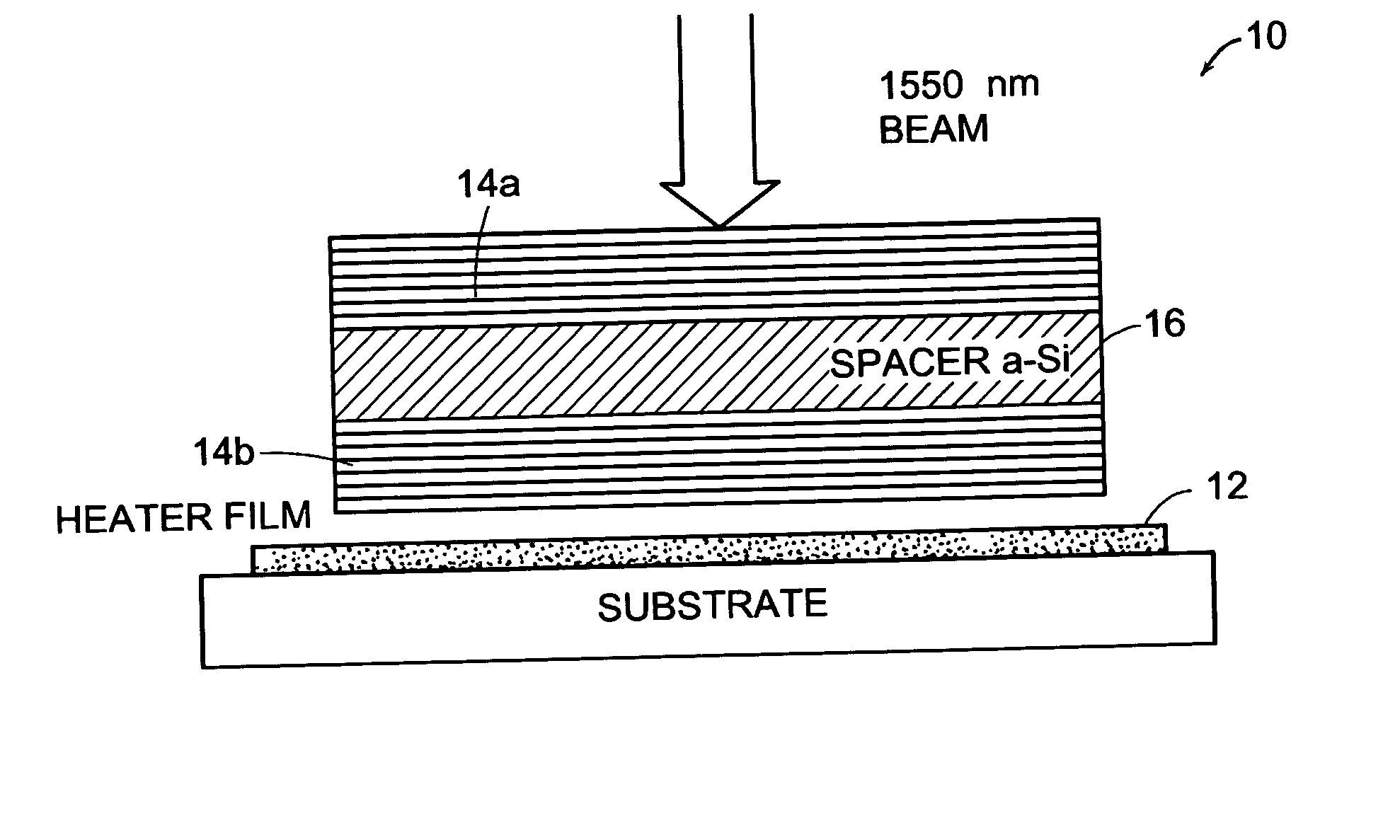
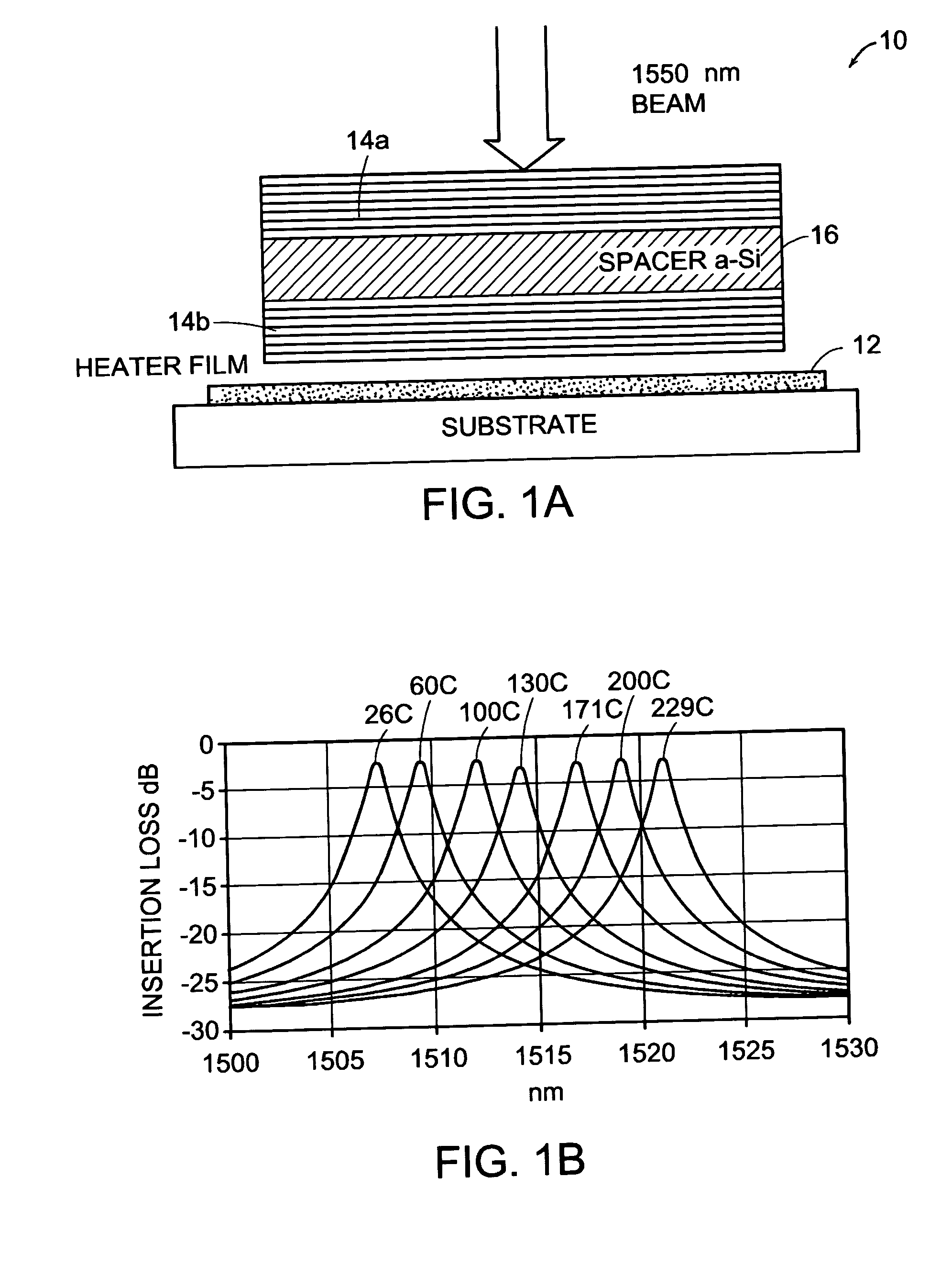
[0025] The first embodiment is a thermo-optically tunable filter formed as a membrane on a silicon frame. The tunable filter which makes up the membrane is fabricated as described in previously filed applications and published articles. In general, it is a multi-layer thin film structure that includes one or more Fabry-Perot cavities, each of which has two thin film interference mirrors separated by a spacer. The mirrors and the spacers are made of a material that has an index of refraction that is characterized by a relatively high thermal coefficient. In this case, that material is amorphous silicon (a-Si), though other materials could also be used such as amorphous germanium (a-Ge). The resulting optical filter has a optical transmission curve with a band pass located at a wavelength that is determined by the design of the structure, e.g. the thickness of the films that make up the multi-cavity structure. By heating and cooling the optical filter...


PUM


Abstract

An optical device including: a substrate with a top surface and a bottom surface and a hole extending through the substrate from the top surface to the bottom surface; and a multilayered thin film structure fabricated on the substrate and forming a membrane over the hole, the multilayered thin film structure including a thermally tunable thin film optical filter structure at least a portion of which is positioned over the hole.

Description

[0001] This application claims the benefit of U.S. Provisional Application No. 60 / 509,379, filed Oct. 7, 2003; and U.S. Provisional Application No. 60 / 509,200, filed Oct. 7, 2003.TECHNICAL FIELD [0002] This invention relates to thermally tunable devices such as thermo-optically tunable thin film optical filters. BACKGROUND OF THE INVENTION [0003] There is a family of devices that are based on thermo-optically tunable, thin-film optical filters. These devices, which are made from amorphous semiconductor materials, exploit what had previously been viewed as an undesirable property of amorphous silicon, namely, its large thermo-optic coefficient. The performance of these devices is based on trying to maximize thermo-optic tunability in thin-film interference structures, instead of trying to minimize it as is often the objective for conventional fixed filters. The devices are characterized by a pass band centered at a wavelength that is controlled by the temperature of the device. In ot...

Claims


Application Information

Patent Timeline
IPC IPC(8): G01J3/10G01J3/12G01J3/26G01J3/433G01N21/35G02B6/34G02B27/00G02F1/01G02F1/21
CPCG01J3/108G01J3/12G01J3/26G01J3/433G02F2202/10G02F1/0147G02F1/21G02F2001/213G01N21/3504G02F1/213
Inventor MA, EUGENE YI-SHANCOHEN, MITCHELL S.HAZELL, JOHN
Owner AEGIS SEMICON
Why Eureka
Try Eureka