Niobium oxide-based layers for thin film optical coatings and processes for producing the same

a technology of niobium oxide and thin film, applied in the direction of liquid/solution decomposition chemical coating, coating, instruments, etc., can solve the problems of increasing the overall cost of the coating system, fewer durable materials with such a specific index of refraction, and using expensive techniques such as vacuum evaporation or sputtering

Inactive Publication Date: 2005-11-03
DENGLAS TECH
View PDF26 Cites 16 Cited by
  • Summary
  • Abstract
  • Description
  • Claims
  • Application Information

AI Technical Summary

Problems solved by technology

However, there are very few durable materials which have such a specific index of refraction (i.e., 1.2288).
However, each layer in a multi-layer coating system increases the overall cost of the coating system.
However, in order to produce durable coating layers of these high index of refraction materials, it is often necessary to use expensive techniques such as vacuum evaporation or sputtering.
The cost of the equipment used in such application processes can often create an economically unviable approach to producing such coatings.
Unfortunately, however, conventional sol-gel processes offer few choices of high refractive index coating materials.
Niobium oxide has been suggested for electrochromic applications, but thus far, it has not been used to produce a high index of refraction layer in thin film optical coatings, except through expensive sputtering and chemical vapor deposition techniques.
Electrochromic coatings are generally designed to be crack-free, but are not concerned with uniformity, or the absorption / transmission of light.
However, since precursor mixtures of silicon and niobium have been found to be unstable when niobium exceeds 10 mole %, these materials have not been heavily investigated.
Precursors with greater than 10 mole % of niobium tend to undergo rapid gelation, rendering them ineffective for most sol-gel techniques.
While, sol-gel preparations have generally become a popular investigative topic in the field of thin film optical coatings, sol-gel niobium oxide materials are not known to have high indices of refraction.
Thus, thin film optical coatings cannot be coated on a large class of materials (i.e., those with melting points below 400° C.) using conventional sol-gel processes.

Method used


Image

  • Niobium oxide-based layers for thin film optical coatings and processes for producing the same
  • Niobium oxide-based layers for thin film optical coatings and processes for producing the same
  • Niobium oxide-based layers for thin film optical coatings and processes for producing the same

Examples


example 1

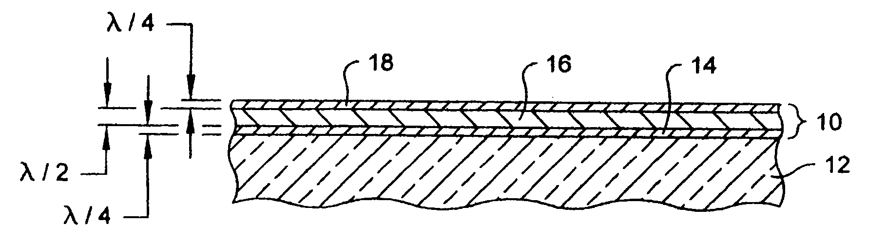
[0047] A mixture for preparing an H-layer was prepared by combining 61 grams of niobium pentachloride and 94 mL of 100% ethanol (anhydrous, denatured ethanol, SDA 2B-2), with stirring. After the niobium pentachloride had reacted with the ethanol, an additional 500 mL of ethanol and 25 mL of deionized water were added to the mixture. The mixture was then diluted to 1000 mL total volume with additional ethanol. This mixture was used in Example 4 to form a layer having an index of refraction of 2.03 on soda-lime float glass, and in Example 5 to form a layer having an index of refraction of 1.96 on polycarbonate.

example 2

[0048] A mixture for preparing an M-layer was prepared as follows: 66 mL of ethanol, 25 mL of tetramethoxysilane, 22 mL of deionized water, and 2.6 mL of glacial acetic acid were mixed at room temperature with constant stirring. During the stirring, the viscosity was measured every hour until a viscosity of approximately 3.0 to 3.2 centistokes was reached, roughly indicating the preferred extent of hydrolysis and condensation. At this point, 0.66 mL of 69% nitric acid were added to the mixture and the mixture was diluted to 1000 mL with additional ethanol. A separate solution was prepared by dissolving 74 grams of aluminum nitrate (Al(NO3)3●9H2O) in 1000 mL of ethanol. The second solution was then added to the previously prepared mixture. Finally, 500 mL of the resulting mixture were mixed with 500 mL of the H-layer mixture prepared in Example 1. This final mixture was used in Example 4 to form a layer having an index of refraction of 1.74.

example 3

[0049] A mixture for preparing an L layer was prepared by mixing 160 mL of ethanol, 93 mL of tetraethoxysilane, 54 mL of deionized water and 1 mL of hydrochloric acid (37%), while stirring at room temperature. During the stirring, the viscosity was measured every hour until a value of 3.0-3.2 centistokes was reached. A second solution was prepared by dissolving 2 grams of aluminum nitrate (Al(NO3)3●9H2O) and 50 mL of ethanol. This solution was mixed with the mixture containing the tetraethoxysilane. The combined mixture was diluted to a final volume of 1000 mL with additional ethanol. This mixture was used in Example 4 to form a layer having an index of refraction of 1.46.


PUM

PropertyMeasurementUnit
concentrationaaaaaaaaaa
speedaaaaaaaaaa
temperatureaaaaaaaaaa

Abstract

The invention includes a thin film optical coating having a layer comprising sol-gel derived niobium oxide which is capable of providing an index of refraction of at least about 1.90. The invention also includes a thin film optical coating having a layer comprising a sol-gel derived oxide system including niobium oxide and a second oxide component such as aluminum oxide and / or silicon oxide which is capable of providing an index of refraction of from about 1.60 to about 1.90. Also included in the present invention are processes for producing such thin film coatings. In the processes, a substrate is immersed in a mixture comprising niobium chloride and an alcohol, withdrawn from the mixture, and heat-treated. The mixture may also include aluminum precursors and / or silicon precursors. The heat-treatment may occur at various temperatures, including those under 200° C.

Description

BACKGROUND OF THE INVENTION [0001] Thin film optical coatings can be used to alter a substrate's optical properties. For example, the reflection of light which occurs at the interface of two different materials may be altered by applying a thin film optical coating to a surface at such an interface. Additionally, the transmission of light can be reduced by an absorbent optical coating or the transmittance / absorbance of specific wavelengths can be enhanced. [0002] It is often desirable to reduce the percentage of visible light which is reflected at an interface and increase the transmittance of visible light, thus reducing glare associated with the reflection of visible light. Antireflection thin film optical coatings for such purposes have numerous applications including, for example, windows, lenses, picture frames and visual display devices such as computer monitors, television screens, calculators and clock faces. [0003] Generally, the reflection of light occurs at the interface ...

Claims


Application Information

Patent Timeline
Patent Type & Authority Applications(United States)
IPC IPC(8): B05D5/06B32B9/00B32B17/06C03C17/25C03C17/27C08J7/06C23C18/12G02B1/11
CPCC03C17/25C03C17/27C03C2217/213C03C2217/214C03C2217/218C03C2217/23G02B1/115C03C2218/32C03C2218/322C08J7/06C08J2369/00C23C18/1216C23C18/1254C03C2218/113
Inventor ARFSTEN, NANNING J.GAVLAS, JAMES F.
Owner DENGLAS TECH
Why Eureka
Try Eureka