Optical information recording method and optical information recording apparatus

a technology of optical information and recording method, which is applied in the field of optical information recording method and optical information recording apparatus, can solve the problems of reducing the fundamental clock period t, increasing the load of the driving unit that drives the optical source, and reducing heating time and cooling time, so as to suppress jitter and high speed. , the effect of high quality

Inactive Publication Date: 2005-05-19
RICOH KK
View PDF10 Cites 28 Cited by
  • Summary
  • Abstract
  • Description
  • Claims
  • Application Information

AI Technical Summary

Benefits of technology

[0043] Accordingly, it is an object of the present invention to provide a method and apparatus enabling repetitive optical recording on an optical recording medium at high speed and with high quality at the time of high-speed recording mode, while suppressing the jitter at the same time.

Problems solved by technology

At the time of high speed recording such as the case of carrying out recording with a speed exceeding the quadruple speed of DVD, on the other hand, it should be noted that the fundamental clock period T is reduced and there is caused an increase of load in the driving unit that drives the optical source.
Further, in the case of irradiating the pulse train of the 1T interval as shown in FIG. 7, both the heating time and the cooling time become reduced when the clock period T is reduced, and there arises a problem in that the amorphous mark having a sufficient size is not formed.
In the case of the recording method that uses a recording strategy shown in the foregoing Patent References 1-3 in which the number of the optical pulses is reduced when forming an amorphous mark, there can arise a problem that the temperature of the recording layer may not become stationary when the optical pulse of the peak power level is irradiated for the formation of the next recording mark in the case the length of the space immediately before the mark is small.
It should be noted that this problem appears particularly conspicuous when the linear recording velocity is increased due to the reduced time for optical irradiation.
As a result of this problem, there occurs a fluctuation in the mark leading edge position at the time the optical beam of the peak power level is irradiated for the next mark formation, and there arises the problem of increased jitter.
In the case of the high speed recording of sixfold to eightfold speed of DVD, in particular, formation of the space region has to be made also in short time and it is believed that this also contributes to the foregoing problem of increased jitter by failing to reach the stationary state.
Further, at the time of the high-speed recording, cooling rate of the optical information recording medium tends to become also insufficient.
Thereby, the jitter of the recording mark is deteriorated.
However, it is difficult to achieve overall balance by a single optical pulse, and it is difficult to achieve satisfactory recording with a random pattern.

Method used


Image

  • Optical information recording method and optical information recording apparatus
  • Optical information recording method and optical information recording apparatus
  • Optical information recording method and optical information recording apparatus

Examples


embodiment

[0116] Hereinafter, the present invention will be explained for a best mode by referring to the drawings.

[0117] The embodiment of the present invention is applicable to an optical information recording method and optical information recording apparatus (including optical information playback apparatus) that records information on an optical information recording apparatus capable of recording, erasing or rewriting information by way of intensity modulation of an irradiated optical beam, particularly an optical information recording medium of the phase change type, with high speed such as sixfold to eightfold speed of a DVD.

[Optical Information Recording Medium]

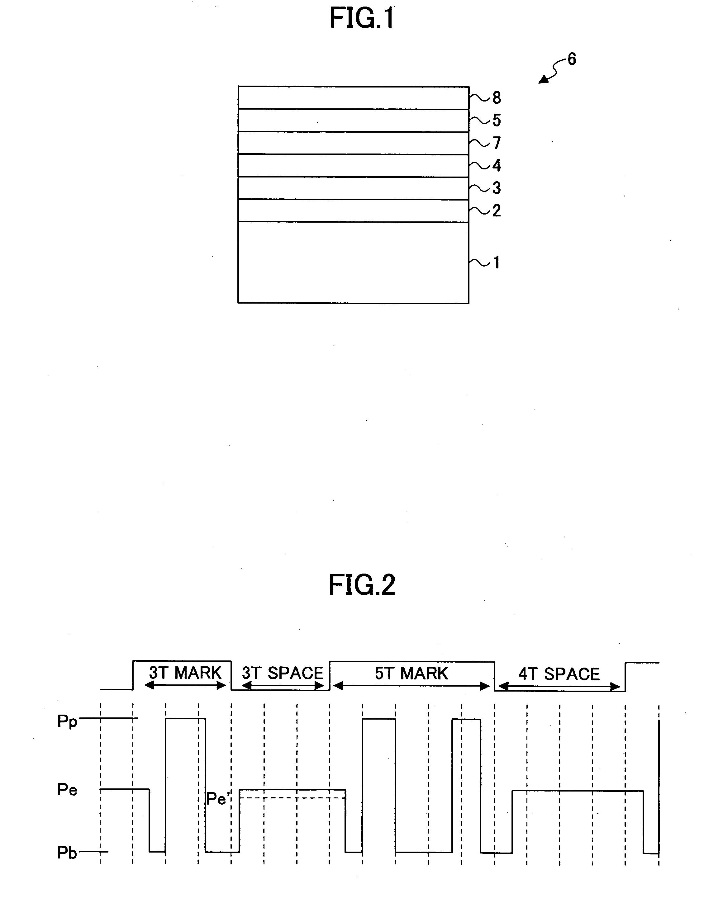
[0118] First, an example of the optical information recording medium of the phase change type of high-speed specification designed for the specification of DVD will be explained with reference to FIG. 1.

[0119] In the present embodiment, an optical information recording medium 6 of the phase change type will be treated, whe...

example 1

[0190]FIG. 2 shows the optical emission waveform pattern of Example 1.

[0191] Referring to FIG. 2, Example 1 uses the recording strategy of using the erasing power level Pe during the formation of the crystalline space region and reduces the optical power to the bottom power level Pb at the time of transition to the state formation of the recording mark.

[0192] In Example 1, the optical information recording medium 6 is constructed on a disk-shaped polycarbonate substrate having a diameter of 12 cm and a thickness of 0.6 mm and formed with guide grooves with the track pitch of 0.74 μm, wherein the polycarbonate substrate is covered with the first protective layer 2 of ZnS—SiO2 with a thickness of 60 nm, and the recording layer 3 of In—Sb—Ge is formed on the first protective layer 2 with the thickness of 15 nm. Further, the second protective layer 4 of ZnS—SiO2 is formed on the recording layer 3 with a thickness of 12 nm, and the sulfuration prevention layer 7 of SiC is formed on the...

example 2

[0200] In Example 2, the same optical information recording medium 6 of Example 1 is used, and recording is carried out according to the strategy shown in FIG. 11 in which it will be noted that the same recording strategy as in the case of FIG. 10 is used in the case of forming a mark pattern after formation of the 3T space region of the shortest length. Otherwise, the no such a modulation of the optical beam power to the bottom power level Pb is made. Thus, the in the case of forming a mark pattern after forming a space region of the 4T or more in the length, there is caused no decrease of the optical beam power after using the erasing optical power Pe. The setting of the various optical power levels is the same also in Example 2.

[0201] After carrying out repetitive recording for ten times, it was confirmed that the overall jitter of the mark edge with respect to the clock takes the value of 9.6%.

[0202] Detailed investigation on the jitter at the mark leading edge formed after th...


PUM

PropertyMeasurementUnit
melting pointaaaaaaaaaa
thicknessaaaaaaaaaa
thicknessaaaaaaaaaa

Abstract

Optical information recording is achieved at high speed such as sixthfold to eightfold speed of DVD while suppressing jitter by a high-speed recording strategy such as a 2T period strategy, by once reducing the optical power of the optical beam used for optical recording, when starting recording of an amorphous mark pattern after the step of forming a crystalline space region but before the step of irradiating the optical beam with a peak power level for the mark formation, such that the optical power of the optical beam is reduced below the erasing optical power used for forming the crystalline space region.

Description

CROSS-REFERENCE TO RELATED APPLICATIONS [0001] The present invention is based on Japanese priority patent application 2003-294100 filed on Aug. 18, 2003, the entire contents of which are incorporated herein as reference. BACKGROUND OF THE INVENTION [0002] The present invention generally relates to optical recording of information and more particularly to optical information recording method and optical information recording apparatus suitable for high-speed optical recording of information on an optical information recording medium, particularly an optical information recording medium of phase change type such as CD-RW, DVD-RAM, DVD-RW, DVD+RW, and the like. [0003] Recently, there is a growing demand of high-speed recoding in the art of optical recording that uses an optical information recording medium. In the case of optical recording that uses a disk-shaped optical information recording medium, increase of recording speed and playback speed is achieved by increasing the rotationa...

Claims


Application Information

Patent Timeline
Patent Type & Authority Applications(United States)
IPC IPC(8): B41M5/26G11B3/00G11B7/0045G11B7/006G11B7/125G11B7/24G11B7/243G11B7/254G11B7/257G11B7/258
CPCG11B7/0062
Inventor HIBINO, EIKOITO, KAZUNORIHARIGAYA, MAKOTOMIURA, HIROSHI
Owner RICOH KK
Why Eureka
Try Eureka