Non-core type bit, non-core drill apparatus, and method of supplying cooling water thereto

a non-core drill and cooling water technology, which is applied in the direction of turning machine accessories, manufacturing tools, transportation and packaging, etc., can solve the problems of reducing affecting the efficiency of boring holes, so as to reduce the absolute amount of cooling water required and the effect of losing cooling water

Inactive Publication Date: 2005-05-19
ISHIHARA KIKAI INDS
View PDF0 Cites 35 Cited by
  • Summary
  • Abstract
  • Description
  • Claims
  • Application Information

AI Technical Summary

Benefits of technology

[0030] In a method of supplying cooling water according to this invention, which is described in claim 18, the supply of cooling water is delayed by a predetermined time from the time when the drill main body starts operating. This prevents the cooling water from leaking to the workpiece or from spilling thereto, and ultimately a loss of the cooling water.
[0031] In a method of supplying cooling water according to this invention, which is described in claims 19 and 20, the cooling water is intermittently supplied to the tip. This decreases the absolute amount of cooling water required.

Problems solved by technology

The muddy water makes the concrete block dirty, particularly at the part that lies around the hole.
This is inevitably because the muddy water is discharged from the hole via the space around the shank.
Since the concrete block gets dirty due to the muddy water discharged via that space, it is necessary to clean the block after the hole has been bored in the block.
This unavoidably reduces the efficiency of boring the hole.
This not only lowers the efficiency of boring holes, but also impairs the work safety.
It would take much time to locate the suction head at the part of the concrete block, not only complicating the hole-boring work, but also decreasing the efficiency thereof.
Further, once the suction head has covered the part of the block, it is no longer easy for the worker to determine the position where the hole is being bored in the block.
Since the suction head needs to cover the concrete block tightly, if the block has rough surface, having recesses and projections, the suction head cannot function as well as is desired, failing to prevent the cooling water from leaking.
Hence, the hole-boring work cannot be carried out in any place where a sufficient supply of cooling water is unavailable.
That is, places where the hole-boring work can be performed are inevitably limited.
The cooling water is thus wasted, not recycled to be used again.
This raises the cost of boring the hole, particularly in the case where liquid dedicated to the cooling of the tip is used as cooling water.

Method used


Image

  • Non-core type bit, non-core drill apparatus, and method of supplying cooling water thereto
  • Non-core type bit, non-core drill apparatus, and method of supplying cooling water thereto
  • Non-core type bit, non-core drill apparatus, and method of supplying cooling water thereto

Examples


first embodiment

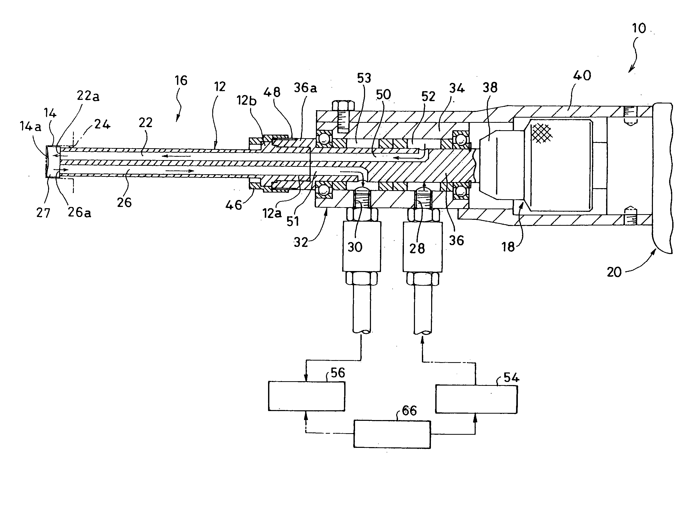
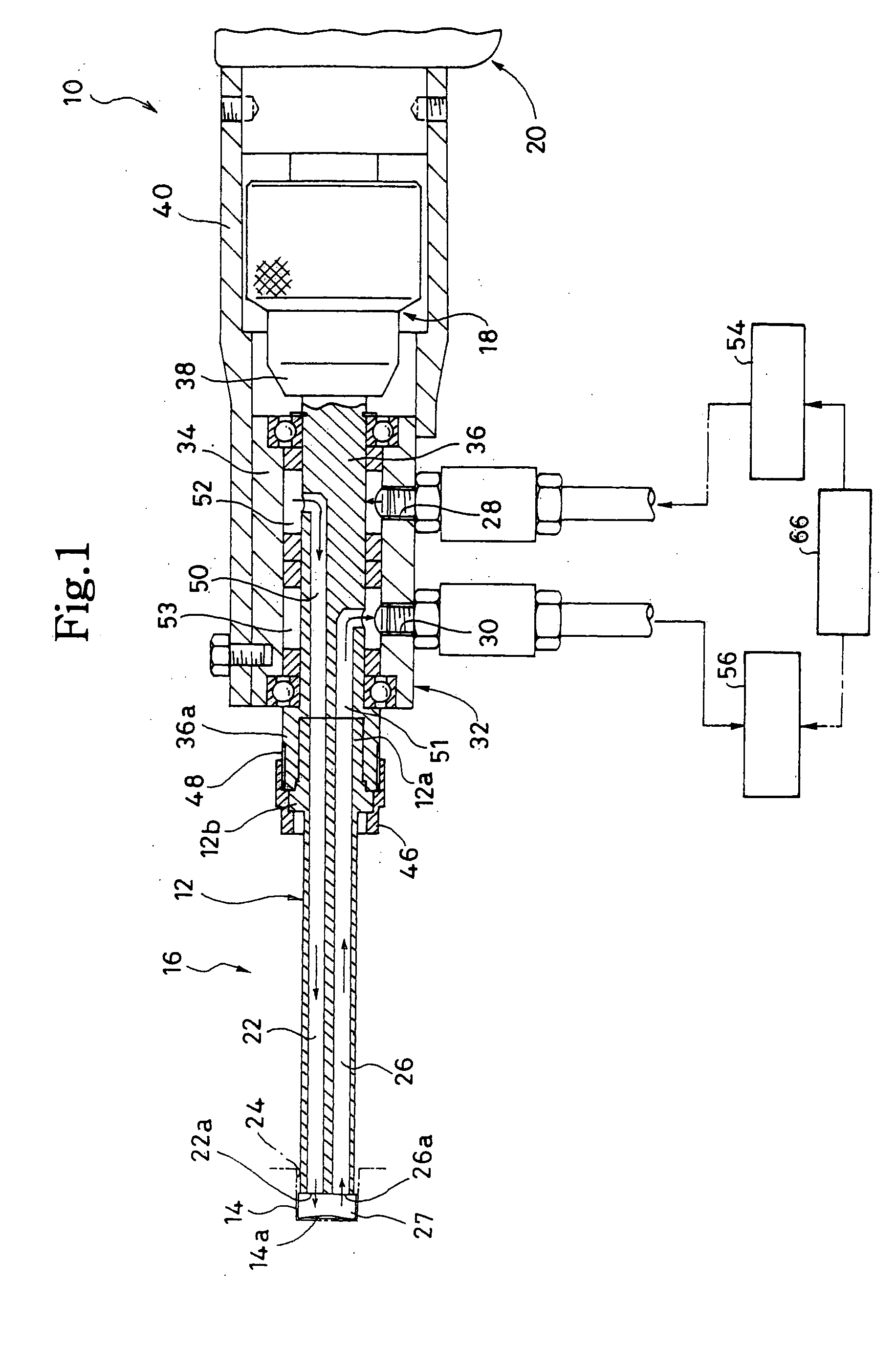
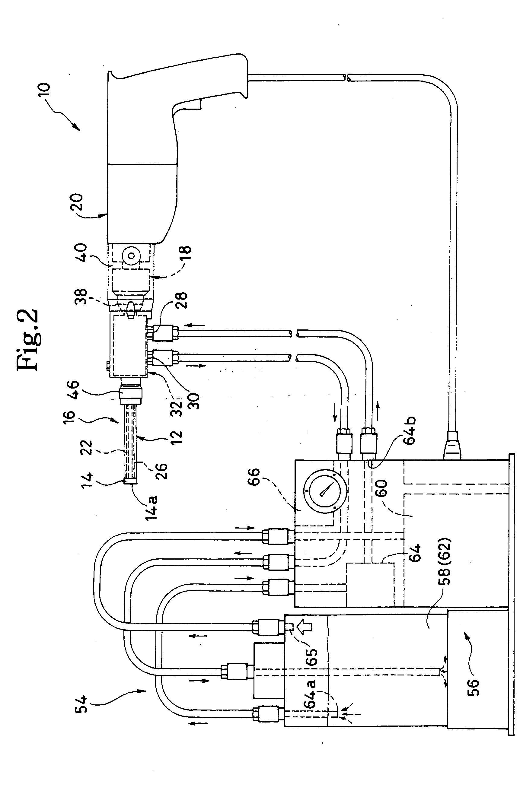
[0040] A non-core drill apparatus 10 according to the invention will be described, with reference to FIGS. 1 and 2. FIG. 1 is a partially sectional view, and FIG. 2 is a schematic representation of the apparatus 10. As FIGS. 1 and 2 show, the non-core drill apparatus 10 comprises a non-core type bit 16 and a drill main body 20. The main body 20 is designed to rotate the non-core type bit 16. The bit 16 includes a shank 12 and a tip 14. The tip 14 is secured to the distal end of the shank 12.

[0041] The drill main body 20 is similar to an electric tool of the known type, such as an electric drill. The main body 20 has a motor (not shown) and a rotary member 18. The rotary member 18 is driven by the motor.

[0042] The tip 14 is made of, for example, sintered diamond. It has a diameter about 1 to 2 mm greater than that of the shank 12.

[0043] The tip 14 includes two tip-strips. The tip-strips are spaced apart, defining a slit 27 between them. The front 14a of the tip 14, i.e., the cuttin...

second embodiment

[0083] In the non-core drill apparatus 10 the inner space of the inner tube 68 serves as water-supplying passage 22, and the gap between the inner tube 68 and the outer tube 70 serves as water-discharging passage 26. The water-supplying passage 22 communicates with the water-supplying port 28 of the swivel 32, and the water-discharging passage 26 communicates with the water-discharging port 30 of the swivel 32. The passages 50 and 52 are thereby provided in the rotary member 36 of the swivel 32.

[0084] The second embodiment is identical to the first embodiment, except for the shank 112. Therefore, the components identical to those of the first embodiment are designated at the same reference numerals and will not be described.

[0085] In the non-core type bit 16 having the double-tube shank 112, too, the shank has a water-supplying passage 22 and a water-discharging passage 26. Hence, the cooling-water discharging means 56 can discharge and recollect the cooling water, by applying a s...


PUM

PropertyMeasurementUnit
diameteraaaaaaaaaa
suction forceaaaaaaaaaa
timeaaaaaaaaaa

Abstract

A cutting tip 14 is secured to the distal end of the shank 12 of a non-core type bit 16 that is designed to bore holes. The shank 12 has a water-supplying passage 22 and a water-discharging passage 26. The water-supplying passage 22 is configured to supply cooling water to the tip 14. The water-discharging passage 26 is configured to discharge the cooling water from a hole 24 being bored by the tip 14. A swivel 32 has a water-supplying port 28 that is connected to a cooling-water source 54. The cooling water flows from the cooling-water source 54 to the bit 14 through the water-supplying passage 22. A suction force applied by a cooling-water discharging means 56 compels the cooling water out of the hole 24. The cooling water is thereby discharged through the water-discharging passage 26.

Description

BACKGROUND OF THE INVENTION [0001] 1. Field of the Invention [0002] The present invention relates to a non-core type bit that has a cutting tip and designed to bore small holes in concrete blocks, a non-core drill apparatus that comprises a non-core type bit of this type, and a method of supplying cooling water to the tip of the non-core drill apparatus. [0003] 2. Description of the Prior Art [0004] So-called non-core type bits and so-called non-core drill apparatuses having a non-core type bit are known. A non-core type bit is used as a drill bit that is used to bore small holes, such as anchor-bolt holes, in concrete blocks (workpieces) such as concrete walls, floor beds or ceiling panels. The non-core type bit can make holes, without leaving cores. A non-core drill apparatus comprises a non-core type bit. Generally known as a non-core type bit includes a shaft-shaped shank and a cutting tip. The tip (diamond tip) is made of sintered diamond and secured to the distal end of the sh...

Claims


Application Information

Patent Timeline
Patent Type & Authority Applications(United States)
IPC IPC(8): B23B51/04B23Q11/00B23B51/06B23Q11/10B28D1/14
CPCB23B51/06B23B2226/75B23Q11/10Y10T408/44B23Q11/1092Y10T408/03B28D1/146Y02P70/10
Inventor ISHIHARA, MASAMITSU
Owner ISHIHARA KIKAI INDS
Why Eureka
Try Eureka