Cell structural body, method of manufacturing cell structural body, and catalyst structural body

a cell structure and cell technology, applied in the field of cell structure, a method for producing the same, and a catalyst structure, can solve the problems of insufficient sealing, isostatic breaking strength, and conventional cell structure cannot meet these demands. achieve the effect of excellent isostatic breaking strength

Active Publication Date: 2005-05-19
NGK INSULATORS LTD
View PDF11 Cites 30 Cited by
  • Summary
  • Abstract
  • Description
  • Claims
  • Application Information

AI Technical Summary

Benefits of technology

[0012] The present invention has been made to solve the above problems, and the object of the present invention is to provide a cell structure which has an excellent isostatic breaking strength and can develop proper sealing function at a cavity, a method for making the same, a catalyst structure, and the like.
[0013] As a result of intensive research conducted by the inventors on behavior of deformation in cell shape around the breaking position of a cell structure having a cavity, the following have been found. That is, since such a cell structure is, for example, a honeycomb structure or a foam structure, the shape of cell is deformed in such a manner that a shear force is applied thereto and the partition wall is appeared to be broken as shown in FIG. 51. Thus, it has been found that the isostatic breaking strength can be increased by making the cell strong in the direction of break line (in the direction shown by the white arrow in FIG. 51).

Problems solved by technology

Thus, the conventional cell structures have a problem in isostatic breaking strength for holding the structure in a container while securing sufficient reliability in endurance.
However, the conventional cell structures cannot sufficiently meet these demands.
That is, sealing is generally carried out by pressing a sealing member to the inner peripheral surface of the cavity at the end face of the cell structure, but in this case the section of the partition wall constituting the cell is a sealing face, and sufficient sealing cannot be performed because the sealing member linearly contacts with the sealing face.
Moreover, sealing force is received only by the partition wall and hence no sufficient pressure can be externally applied to the outer peripheral surface due to the restriction in mechanical strength.

Method used


Image

  • Cell structural body, method of manufacturing cell structural body, and catalyst structural body
  • Cell structural body, method of manufacturing cell structural body, and catalyst structural body
  • Cell structural body, method of manufacturing cell structural body, and catalyst structural body

Examples


example

[0179] The present invention will be further specifically explained by the following examples, which should not be construed as limiting the invention in any manner.

examples 1-7

[0180] A ceramic material (raw material for molding) 52 comprising a mixture of talc, kaolin and alumina as cordierite raw materials, water, a binder, etc. was extruded from die 50 having a plurality of grooves formed in the form of slit 51 shown in FIGS. 49(a)-(d), followed by firing to produce a cordierite ceramic honeycomb structure having a plurality of cells partitioned with partition walls. In this case, press platen 53 for the formation of inner wall corresponding to the shape of the inner wall (in the shape of a disc in FIG. 49(a)) was disposed above the central part of the end face of the die 50 on the side from which ceramic material 52 was extruded, and a guide 58 of conical shape for attaining uniform flowing of ceramic material 52 was disposed underneath the press platen 53 for the formation of inner wall, and, in this state, ceramic material 52 was extruded from grooves formed in the form of slit 51 of die 50, whereby a cavity was formed simultaneously with molding of ...

example 8

[0184] A cell structure was obtained in the same manner as in Example 1, except that the shape of the die used in Example 1 was changed so that the resulting cell structure had a thick wall portion (padded portion) formed at the portion with which the inner wall contacted and, furthermore, a reinforced structure provided by forming a curving part at the corner of points of intersection of partition walls.


PUM

PropertyMeasurementUnit
porosityaaaaaaaaaa
porosityaaaaaaaaaa
porosityaaaaaaaaaa

Abstract

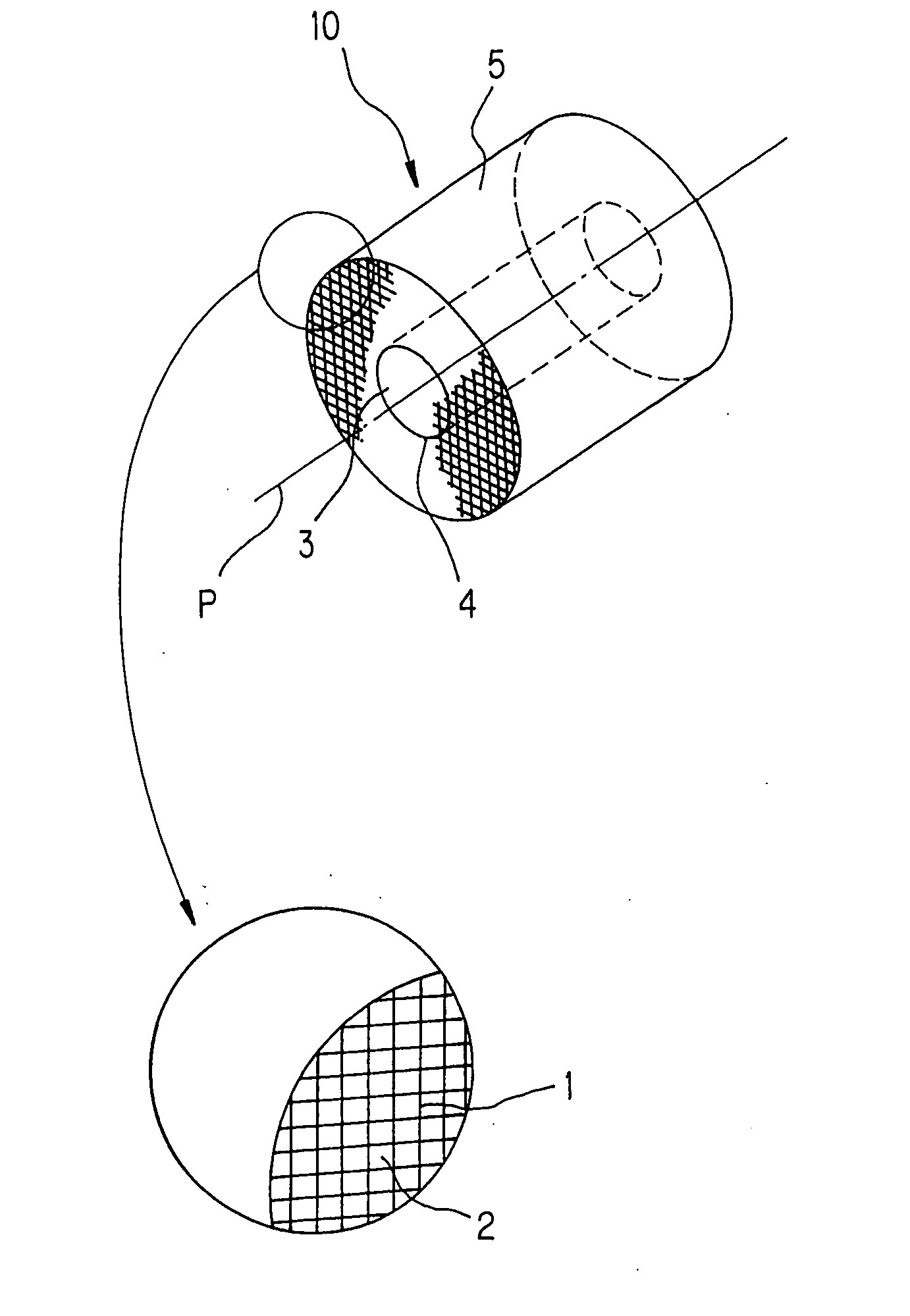
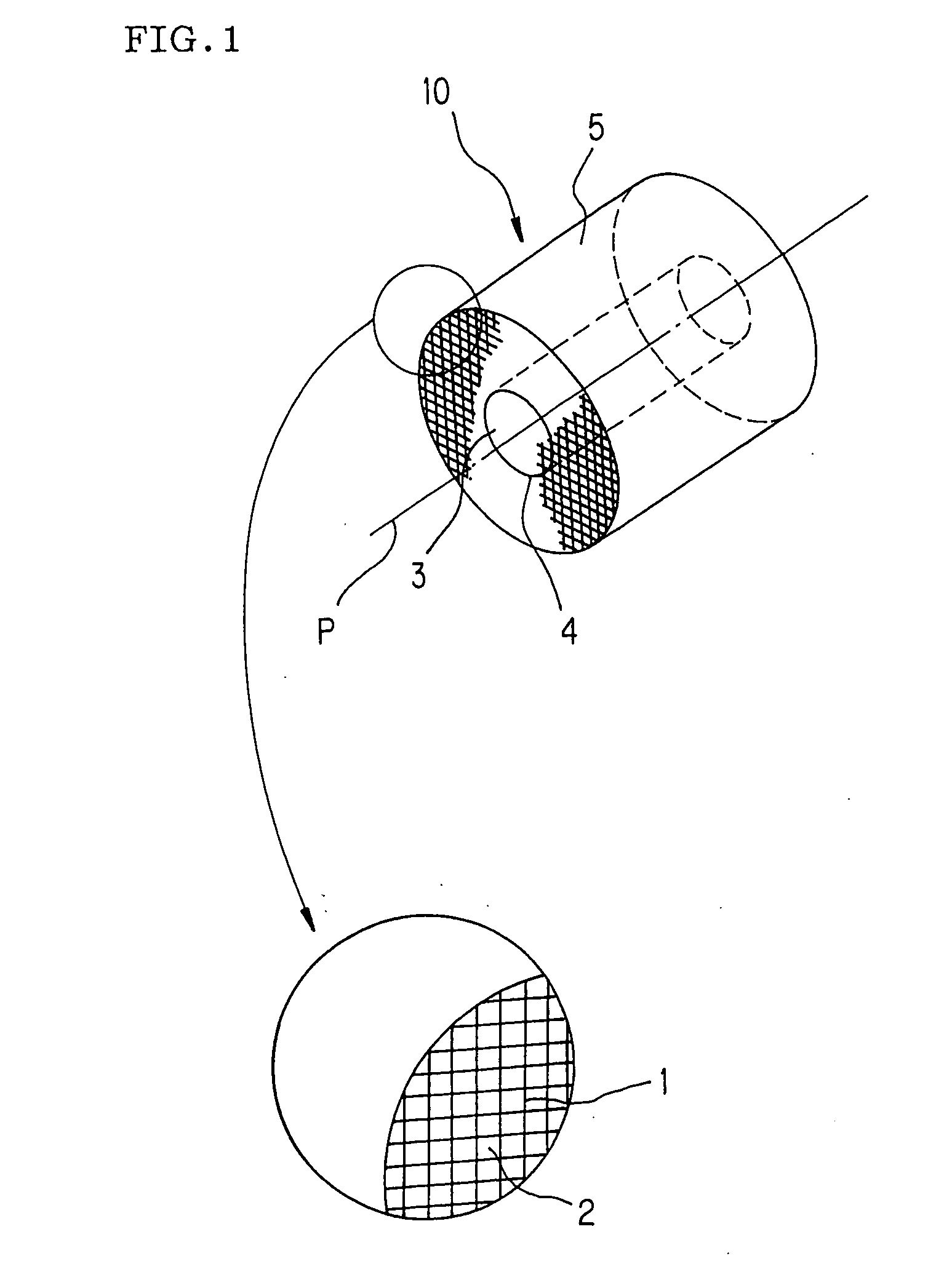
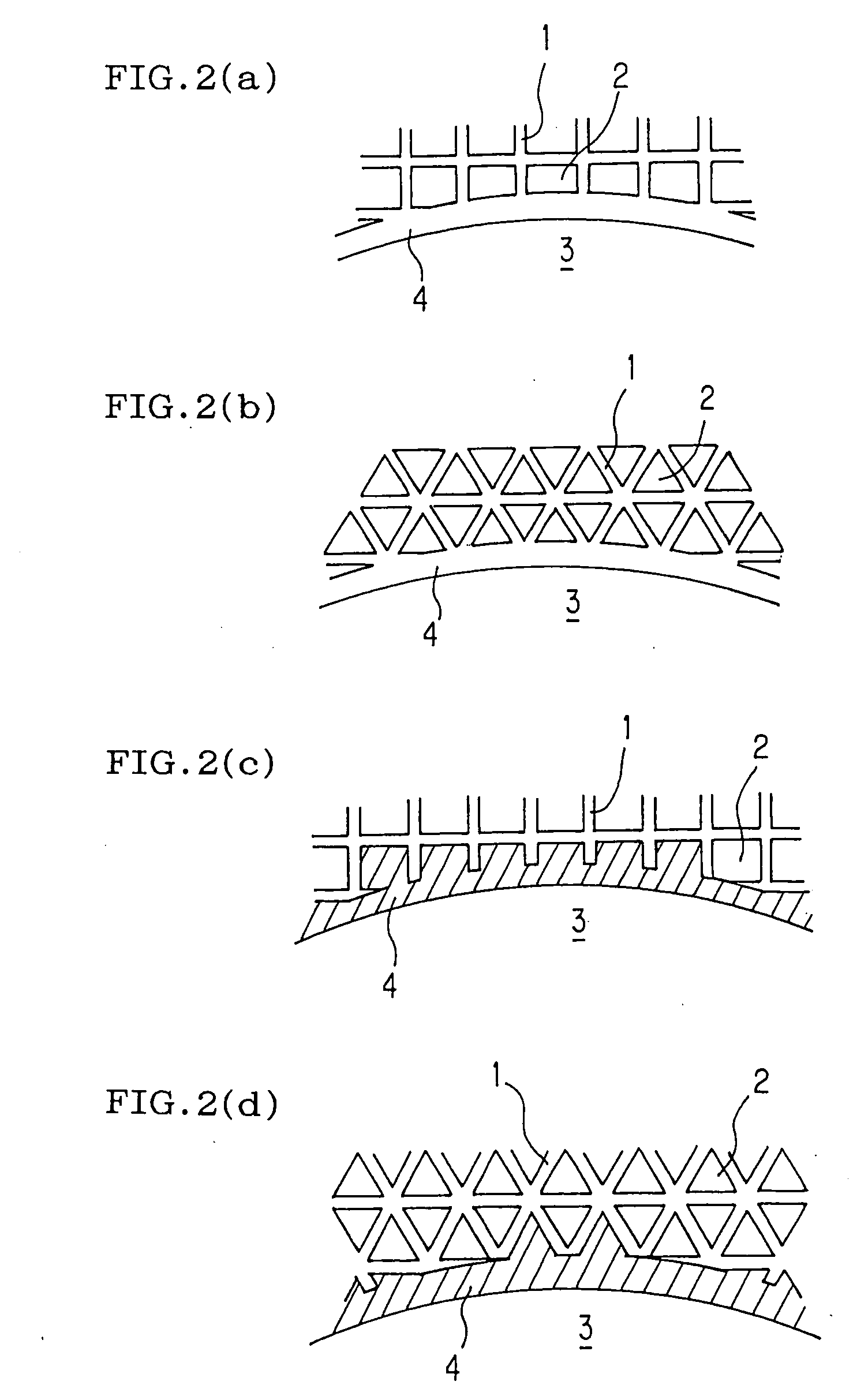
A cell structure 10 having a plurality of cells 2 which are partitioned with partition walls 1 to form a honeycomb and which are flow paths of fluid, an outer wall 5 which encloses the cells 2 and a cavity 3 which pierces in the direction of a central axis P of the structure through a portion including the central axis P or a given axis parallel to the central axis P, where the cell structure further has an inner wall 4 on the inner surface of the cavity 3, a method for producing the cell structure, and a catalyst structure. The cell structure having the cavity has an excellent isostatic breaking strength and can exhibit proper sealing function in its cavities. Furthermore, a method for producing the cell structure, the catalyst structure, etc. are provided.

Description

TECHNICAL FIELD [0001] The present invention relates to a cell structure, a method for producing the same, a catalyst structure, etc. More particularly, it relates to a cell structure which has an excellent isostatic breaking strength and can exhibit proper sealing function in its cavity, a method for producing the cell structure, a catalyst structure, etc. BACKGROUND ART [0002] Hitherto, cell structures a having cavity in the form of being bored in the direction of central axis (for example, honeycomb structures) have been used for various uses. For example, there is disclosed an adsorption-device which has a bypass mechanism for internal combustion engines and which has such a construction that at the time of cold starting, hydrocarbons contained in an exhaust gas from internal combustion engines (for example, automobiles) are adsorbed to an adsorptive material supported on cell partition walls by passing the gas through a cell portion of a honeycomb structure, and thereafter the ...

Claims


Application Information

Patent Timeline
Patent Type & Authority Applications(United States)
IPC IPC(8): B01D53/88B01D53/94B01J35/04F01N3/28
CPCB01D53/885B01D53/94B01J35/04Y10T428/24149B01D46/247B01D2046/2496B01D46/2466F01N3/2828B28B3/269B01D46/2498B01D46/2484B01D46/2482B01D46/2492B01D46/2474B01D46/249B01D46/2455B01D46/2488
Inventor ICHIKAWA, YUKIHITOMIYAZAKI, MAKOTOKATO, YASUSHI
Owner NGK INSULATORS LTD
Why Eureka
Try Eureka