Unlock instant, AI-driven research and patent intelligence for your innovation.

Arrangement and method for illuminating the lens of the human eye

Active Publication Date: 2005-05-19
CARL ZEISS JENA GMBH +1
View PDF7 Cites 9 Cited by
  • Summary
  • Abstract
  • Description
  • Claims
  • Application Information

AI Technical Summary

Benefits of technology

[0010] It is the primary object of the present invention to develop a method and an arrangement for illumination and irradiation of a human eye for therapeutic purposes and for correcting the characteristics of photosensitive plastics already implanted in the eye. An optimized visual acuity is adjusted in the patient by means of this correction, so that additional aids such as eyeglasses or contact lenses need not be worn.

Problems solved by technology

With implanted IOLs, the problem exists that in approximately 50% of patients an acceptable visual acuity can be achieved only through additional corrective measures such as eyeglasses or contact lenses.
This is the result, in part, of errors in eye measurements, deviations in the positioning of the IOL and / or is due to the healing process.
However, there are disadvantages to arrangements of the kind described above in that the supply of patterns is limited by fixed diaphragms, there is no possibility of intensity distribution within the diaphragm patterns, and dynamic processes can be realized, at best, through manual switching and, therefore, hardly at all.
Moreover, the generated illumination patterns can not be adapted to individual findings and are not adaptive or suitable for online regulation.
Inevitably, however, the eyeball must usually be fixated for the duration of the treatment.
However, this solution has disadvantageous results in that there is only one fixating light for the patient.
Experience has shown that it is difficult for the patient to concentrate on a stationary fixating light for the duration of treatment, so that movements of the eye can nevertheless occur.

Method used


Image

  • Arrangement and method for illuminating the lens of the human eye
  • Arrangement and method for illuminating the lens of the human eye
  • Arrangement and method for illuminating the lens of the human eye

Examples


Embodiment Construction

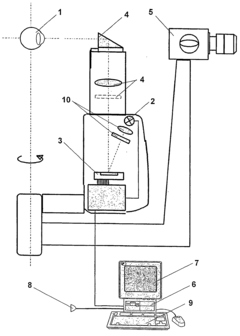
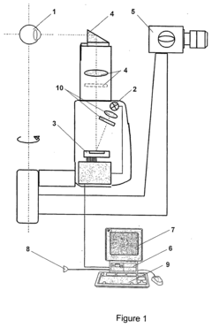
[0018]FIG. 1 shows the basic construction of the arrangement according to the invention for generating an illumination which is variable with respect to time and / or space for diagnosis and therapy, particularly of the human eye 1.

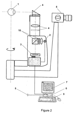
[0019] The arrangement substantially comprises an illumination unit, an optical imaging system 4, an evaluating unit, a central control unit 6 and an output unit 7. The illumination unit comprises an illumination source 2 and an optoelectronic component 3. The illumination source 2 is controllable with respect to its intensity and duration and, for this purpose, possesses additional means for controlling and monitoring the emitted light. A lamp or laser source which is controllable with respect to the spectral composition of the light bundle is used as illumination source 2. The control of the spectral composition can be carried out by means of a filter wheel (not shown). A DMD (digital micromirror device) microdisplay is used as optoelectronic component 3...


PUM


Abstract

The present invention is directed to an arrangement for generating a variable illumination and irradiation for diagnosis and therapy, particularly for the human eye (1), and to a method for the application thereof. The object to be illuminated can be an artificial object or biological tissue. The arrangement for carrying out the illumination / irradiation of a human eye (1) comprises an illumination unit (2, 3), an optical imaging system (4), an evaluating unit, a central control unit (6) and an output unit (7). The illumination unit (2, 3) generates an illumination which is variable with respect to time and / or space and which is adapted to the diagnostic results. The solution according to the invention is provided chiefly for post-operative fine adjustment of the refractive power of photosensitive plastics already implanted in the eye (1). The latter can be optical lenses as well as other optical elements which are placed in a specific manner in the cornea. However, application of the invention for achieving dermatological effects is also conceivable.

Description

CROSS-REFERENCE TO RELATED APPLICATIONS [0001] This application claims priority of International Application No. PCT / EP03 / 00129, filed Jan. 9, 2003 and German Application No. 102 00 718.7, filed Jan. 10, 2002, the complete disclosures of which are hereby incorporated by reference. BACKGROUND OF THE INVENTION [0002] a) Field of the Invention [0003] The present invention is directed to an arrangement for generating a variable illumination and irradiation for diagnosis and therapy, particularly for the human eye, and to a method for the application thereof. The object illuminated by the variable illumination can be an artificial object or biological tissue. However, with respect to the eye, it is also possible to irradiate other parts of the eye besides the lens, such as the cornea, retina or fundus. In particular, the invention can be used for fine adjustment of photosensitive plastics introduced into the eye (according to WO 00 / 41650 and WO 01 / 71411). With plastics of this type, the ...

Claims


Application Information

Patent Timeline
IPC IPC(8): A61B3/12A61B3/117A61B3/135A61F2/16A61F9/007
CPCA61B3/135A61B3/1173A61B3/0008
Inventor WROBEL, WALTERKOSCHMIEDER, INGODONNERHACKE, KARL-HEINZ
Owner CARL ZEISS JENA GMBH