Generator control system, generating apparatus control method, program and record medium

a technology of generating apparatus and control system, which is applied in the direction of adaptive control, electric generator control, instruments, etc., can solve the problems of surplus power generation, long time taken by generators from the start until, and does not suitably follow the load fluctuation of household electrical appliances used, so as to reduce running costs and maximize the merit of household utility charges , the effect of excellent responsiveness

Inactive Publication Date: 2005-05-19
PANASONIC CORP
View PDF11 Cites 59 Cited by
  • Summary
  • Abstract
  • Description
  • Claims
  • Application Information

AI Technical Summary

Benefits of technology

[0083] The present invention provides a generator control system, a generator control method, a program and a record excellent in responsiveness as a response command to the electric load fluctuation of the household electrical appliances and capable of outputting a command value by estimating an electric load value more accurately so as to control the output of the generator in response to the change of settings of the electric power unit.
[0084] Since it is controlled to correspond an increasing amount of the power consumption of the apparatus with the increasing amount of the generating capacity of the generator, the present invention can also provide the generator control system, g...

Problems solved by technology

However, these generators take a long time from a start until reaching a desired output, and does not follow suitably the load fluctuation of household electrical appliances used in the general household.
Therefore, a shortage of the output arises in the case where the electric load is on the increase, and so there is a problem that commercial power is bought from a power company each time and there is no cost merit.
In the case of turning off an apparatus consuming a large amount of power such as the air conditioner, it is impossible, in the conventional example in which a response command is issued after the electric load starts fluctuation, to immediately issue the output control command thereto to control the output of the generator to follow the electric load fluctuation and there is a problem that surplus power is generated.
In this case, there is a problem that there is no guarantee of a unit price of the surplus power accepted by the outside power company being equal to or more than a generation cost of the generator, and so the more power is sold, the more money is lost.
However, there is a problem that introduction of the accumulator requires a significant amount of initial cost and the introduction thereof to the general household is not realistic.
In the case of oper...

Method used


Image

  • Generator control system, generating apparatus control method, program and record medium
  • Generator control system, generating apparatus control method, program and record medium
  • Generator control system, generating apparatus control method, program and record medium

Examples


first embodiment

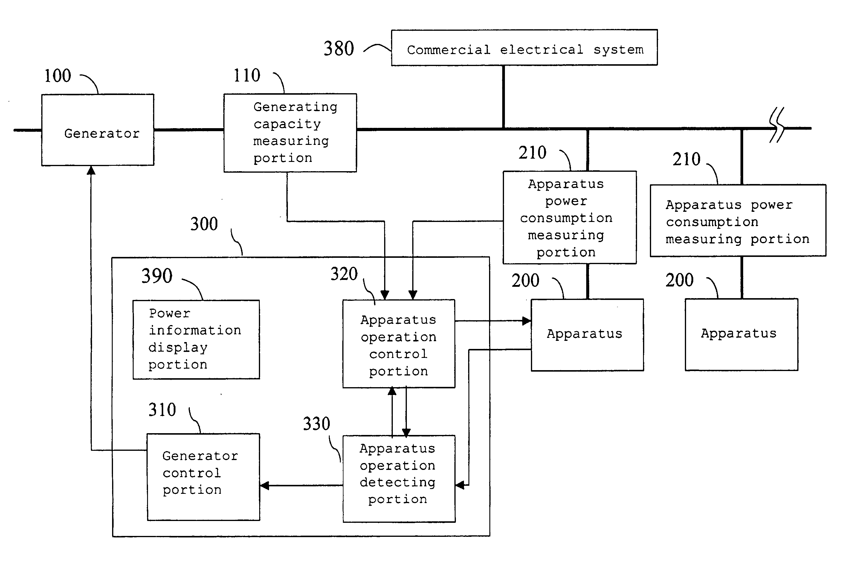
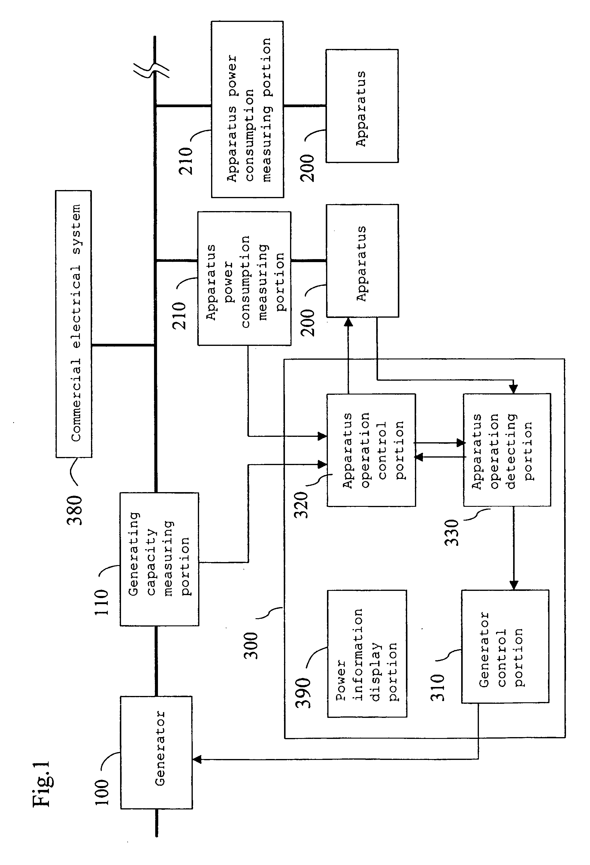
[0108]FIG. 1 is a block diagram of a generator control system according to this embodiment.

[0109] In FIG. 1, a generator 100 is comprised of a fuel battery, a gas turbine, a gas engine and so on. A generating capacity measuring portion 110 is an apparatus which is mounted on an output line of the generator 100 and measures a generating capacity of apparatuses 100. The generating capacity in this case refers to instantaneous power generated by the generator 100.

[0110] The apparatuses 200 are general apparatuses used in a household such as an air conditioner, heating apparatuses and lighting, and an apparatus power consumption measuring portion 210 is an apparatus of measuring power consumption of the apparatuses 200. There are pluralities of the apparatuses 200 and apparatus power consumption measuring portions 210 respectively. Power sensors and so on are used as both the generating capacity measuring portion 110 and apparatus power consumption measuring portions 210.

[0111] The g...

second embodiment

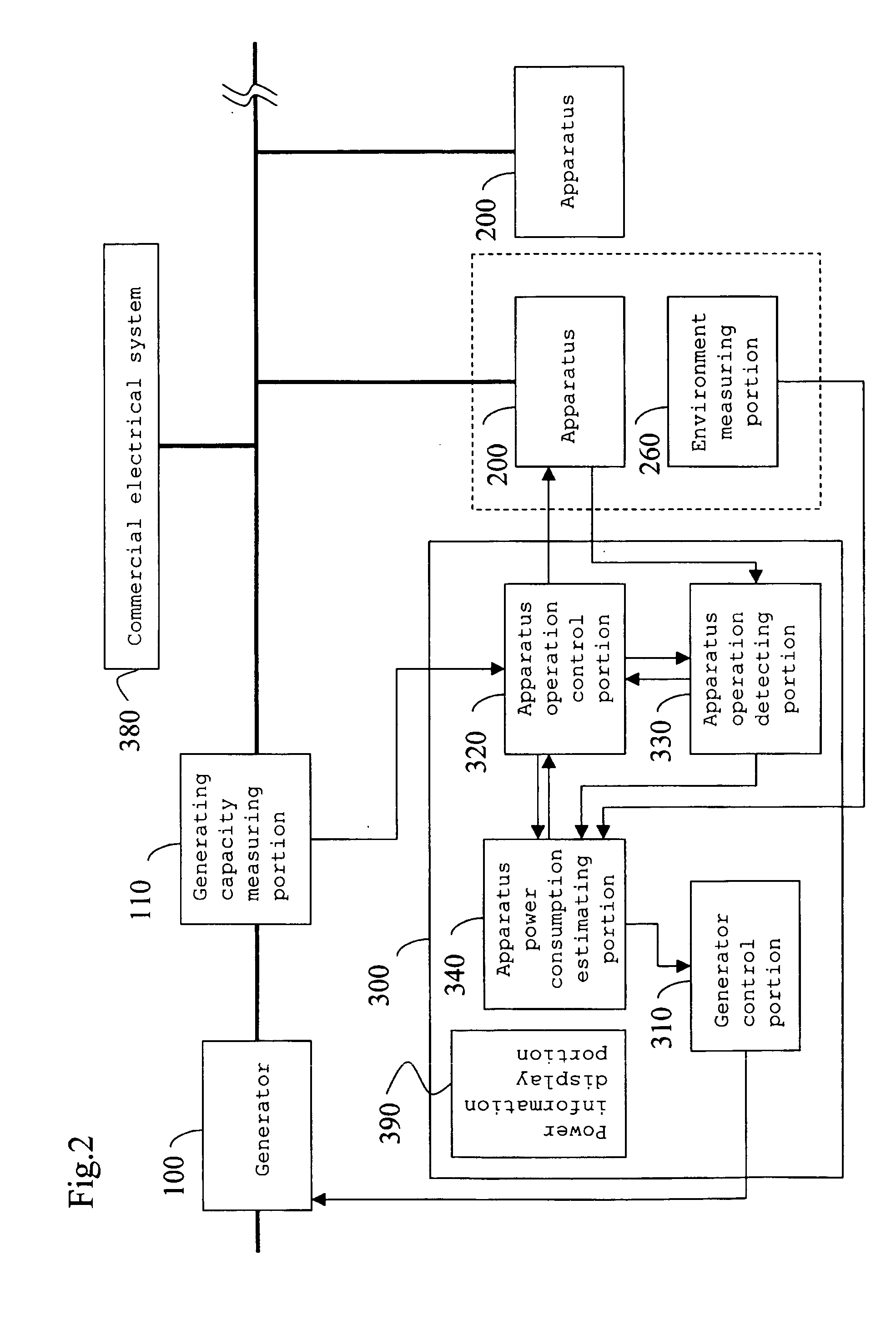
[0150] Next, a second embodiment will be described. According to the first embodiment, there are the cases where, due to the control of the apparatus operation control portion 320, the power consumption of the apparatus 200 temporarily exceeds the generating capacity of the generator 100 so that it is necessary to have the commercial power temporarily supplied from the commercial electrical system 380. As opposed to this, the second embodiment will describe the generator control system which estimates the power consumption of the air conditioner 200 and controls the set state (setting parameters) of the apparatuses 200 by using the result of estimation so that the power consumption of the air conditioner 200 does not exceed the generating capacity of the generator 100 as much as it does in the first embodiment and so it is less likely than the first embodiment to have the commercial power supplied from the commercial electrical system 380.

[0151]FIG. 2 is a block diagram of a genera...

third embodiment

[0175] Next, a third embodiment will be described. The second embodiment described the case of estimating the power consumption of the apparatus 200 and controlling the set state (setting parameters) of the apparatus 200 by using the estimation result. In addition to the case of the second embodiment, the third embodiment describes the generator control system of further measuring the power consumption of the apparatus 200 and improving estimation accuracy of the power consumption of the apparatus 200 by using the measurement result.

[0176]FIG. 3 is a block diagram of the generator control system according to this embodiment.

[0177] In FIG. 3, the apparatus power consumption measuring portions 210 exists as compared to the configuration in FIG. 2. As the configuration is the same as that of the second embodiment otherwise, a description thereof will be omitted.

[0178] Next, the operation of this embodiment having the above configuration will be described by centering on the differen...


PUM


Abstract

In the case where a user changes a set state of apparatuses, an apparatus operation control portion repressively controls the apparatuses, in spite of an instruction of a control signal according to that change, so that an increasing amount of power consumption of the apparatuses obtained from an apparatus power consumption measuring portion will not exceed an increasing amount of the generating capacity of a generator obtained from a generating capacity measuring portion so as to gradually bring it closer to a target set state set up by the user.

Description

BACKGROUND OF THE INVENTION [0001] 1. Field of the Invention [0002] The present invention relates to a generator control system, a generator control method, a power control system, a power control method, a program and a record medium of matching an electric load of household electrical appliances to an output of a generator. [0003] 2. Related Art of the Invention [0004] On introducing a fuel battery or generators such as those using a gas engine and a gas turbine to a household, what should be considered is a scale of electric load fluctuation in a general household. In these generators, improvement in total energy utilization efficiency can be expected when effectively using waste heat together with a generating capacity. However, these generators take a long time from a start until reaching a desired output, and does not follow suitably the load fluctuation of household electrical appliances used in the general household. [0005] As a method of following the electric load fluctuat...

Claims


Application Information

Patent Timeline
IPC IPC(8): H02J3/14H02J3/38H02P9/00
CPCH02J3/14Y04S20/222Y02B70/3225H02J3/38H02J2310/62
Inventor MATSUI, MASARUNISHITANI, KAZUHIRONOGUCHI, EIJI
Owner PANASONIC CORP
Why Eureka
Try Eureka