Coating rod and producing method therefor

a technology of coating rods and coating surfaces, applied in manufacturing tools, lapping machines, ways, etc., can solve the problems of scratches, surface irregularities of treatment layers, sharp tips, etc., and achieve the effect of preventing scratches and coating unevenness

Inactive Publication Date: 2005-05-26
FUJIFILM CORP
View PDF2 Cites 8 Cited by
  • Summary
  • Abstract
  • Description
  • Claims
  • Application Information

AI Technical Summary

Benefits of technology

[0011] In view of the foregoing, it is a primary object of the present invention to provide a coating rod and a producing method therefor in which scratches and coating unevenness are prevented from occurring and a trial of coating is unnecessary.

Problems solved by technology

However, the surface of the treatment layer has minute irregularity of which the tip is sharp.
Thus, if coating is performed as it is, there arises a problem in that scratches are caused on a coating surface.
When the convexities have uneven height, there arises a problem in that the highest portion partially abuts on the web to cause scratches.
In the meantime, when the coating film having hardness and abrasion resistance is used, the sharp tip and the highest portion are hardly abraded so that the scratch is caused for a long time.
Thus, defective products occur at a certain rate.

Method used


Image

  • Coating rod and producing method therefor
  • Coating rod and producing method therefor
  • Coating rod and producing method therefor

Examples


example 1

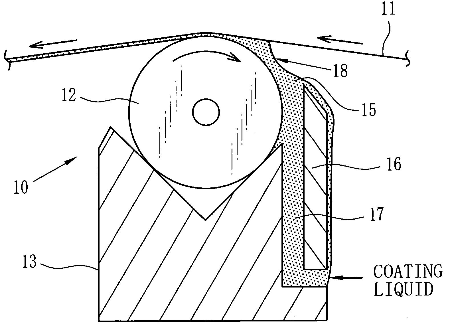
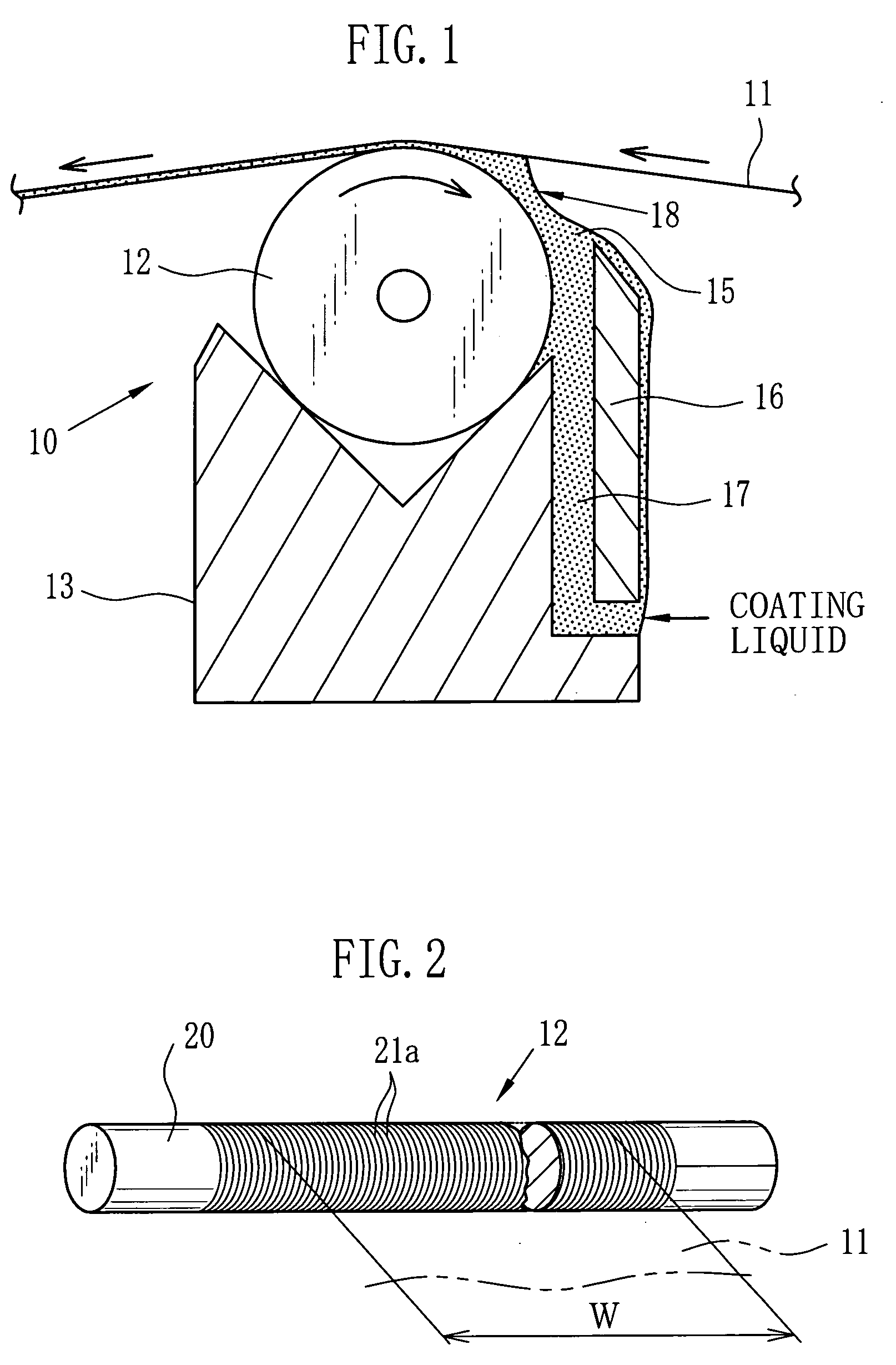
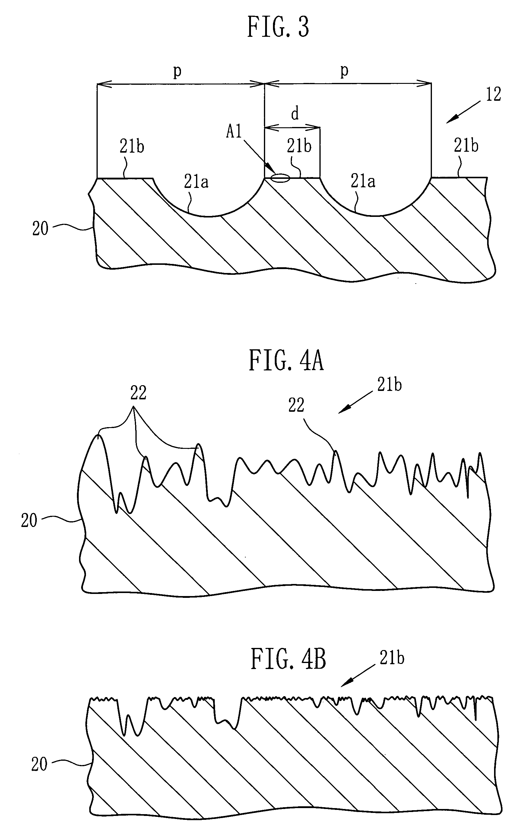
[0057] The concave portions 21a and the convex portions 21b were formed on the surface of the stainless-steel rod 20 by the component rolling method, such as shown in FIG. 3. This rod 20 for which hard chrome-plating of 12 μm was carried out was ground by the grinding apparatus 30 at the final step to produce the coating rod 12 having the following factors. This coating rod 12 was attached to the rod coater 10 shown in FIG. 1, and the web was advanced at a line speed of 90 m / min. And then, coating was performed by rotating the rod 20 at a peripheral velocity of 1 m / min in a reverse direction to the web advancement direction. After drying the web, samples of Nos. 1 to 8 were obtained. The coating surfaces of the samples of Nos. 1 to 8 were visually observed to estimate the scratches and the coating unevenness. Experimental results of this example are shown in Table 1.

TABLE 1RySTROSa1 / Sa2Judgment Result ofNo.[μm]D / W[μm][μm][%]Coating Surface10.20.005502080Scratches of whole areaHeav...

example 2

[0061] The concave portions 21a and the convex portions 21b were formed on the surface of the stainless-steel rod 20 by the component rolling method. This rod 20 for which hard chrome-plating of 12 μm was carried out was ground at the final step to produce the coating rod 12 having the following factors. This coating rod 12 was attached to the rod coater 10 shown in FIG. 1, and the web was advanced at a line speed of 60 m / min. And then, coating was performed by rotating the rod 20 at a peripheral velocity of 60 m / min in the same direction with the web advancement direction. After drying the web, samples of Nos. 11 to 18 were obtained. The coating surfaces of the samples of Nos. 11 to 18 were visually observed to estimate the scratches and the coating unevenness. Experimental results of this example are shown in Table 2. In Example 2, the web advancement speed is identical with the peripheral velocity of the rod, and the web advancement direction is the same with the rotational direc...


PUM

PropertyMeasurementUnit
height Ryaaaaaaaaaa
widthaaaaaaaaaa
roughnessaaaaaaaaaa

Abstract

A peripheral surface of a coating rod has an area where grooves (convex portions) are formed. This area is ground by a grinding apparatus by which a maximum height Ry of the rod surface is adjusted to 15 μm or less. Further, a ratio of D/W is adjusted to 0.01 or more, wherein D is a total distance of the convex portions of the rod actually abutting on a web in an axial direction of the rod, and W is a coating width of the web. Furthermore, straightness of the rod is adjusted to 30 μm or less per 1 m, and roundness of the rod is adjusted to 10 μm or less. Micro-projections are removed by grinding so that scratches of a coating surface are prevented from occurring. Coating unevenness is prevented by improving the straightness and the roundness.

Description

BACKGROUND OF THE INVENTION [0001] 1. Field of the Invention [0002] The present invention relates to a coating rod and a producing method therefor, and in particular relates to a coating rod for coating various kinds of liquid substance (coating liquid) on a material to be coated (hereinafter called as web), and for smoothing the liquid substance after coating. The material to be coated is a thin metal plate, a paper, a film and so forth having a sheet shape or a web shape. [0003] 2. Description of the Related Art [0004] With respect to coating apparatuses for applying various sorts of coating liquids to a web of a thin metal plate, a paper, a plastic film and so forth, various kinds of apparatuses are known. For example, there are a roll coater, an air knife coater, a coater using a die, and a rod coater. [0005] Among the coating apparatuses, the rod coater is widely utilized, since this coater is a simple coating apparatus and is capable of applying the various sorts of the coatin...

Claims


Application Information

Patent Timeline
Patent Type & Authority Applications(United States)
IPC IPC(8): B05C1/08B05C11/02
CPCB05C11/025B05C1/0808B24B37/02
Inventor OOSHIMA, ATSUSHIMATSUMOTO, SATORUNARUSE, YASUHITO
Owner FUJIFILM CORP
Why Eureka
Try Eureka