Fuel injection system and method

a fuel injection system and fuel injection technology, applied in the direction of engine starters, machines/engines, electric control, etc., can solve the problems of not maintaining sufficient engine startability, only possible reducing so as to reduce the emission of smoke, the effect of sufficient engine startability and significant reduction of smoke emission

Inactive Publication Date: 2005-05-26
TOYOTA JIDOSHA KK
View PDF8 Cites 115 Cited by
  • Summary
  • Abstract
  • Description
  • Claims
  • Application Information

AI Technical Summary

Benefits of technology

[0012] Thus, according to the first aspect of the invention, when the engine temperature is equal to or lower than the predetermined temperature during an engine start-up period, lower octane fuel is injected via the first fuel injector, giving priority to maintaining a sufficient engine startability over reducing the emission of smoke.

Problems solved by technology

Thus, the aforementioned significant reduction in the emission of smoke while maintaining a sufficient engine startability is only possible when the engine temperature is relatively high.
That is, if higher octane fuel is injected from the second fuel injector

Method used


Image

  • Fuel injection system and method
  • Fuel injection system and method
  • Fuel injection system and method

Examples


Embodiment Construction

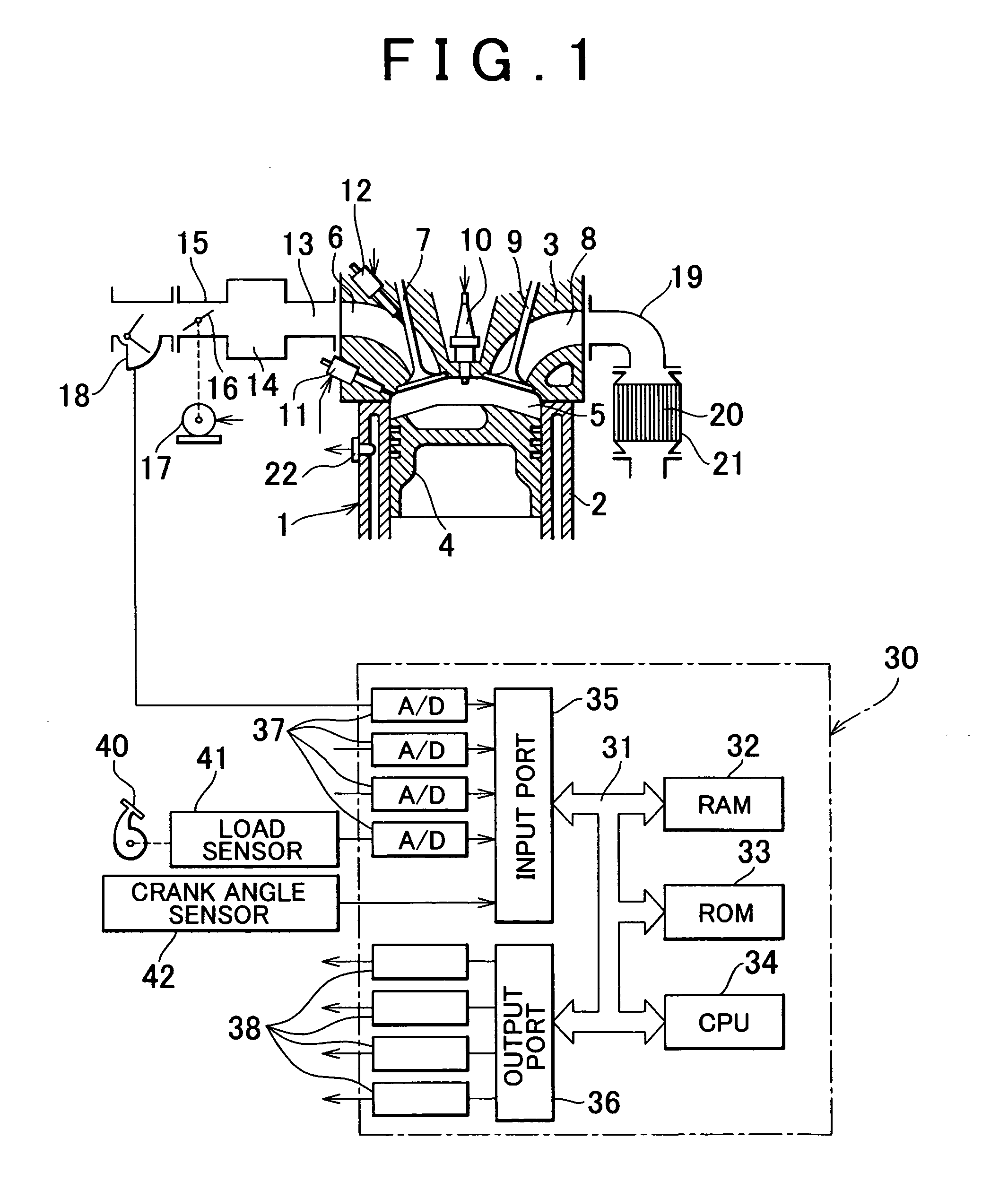
[0020] Hereinafter, a fuel injection system according to an exemplary embodiment of the invention will be described with reference to the accompanying drawings. FIG. 1 schematically shows the configuration of an internal combustion engine 1 incorporating the fuel injection system of this exemplary embodiment. The engine 1 includes a cylinder block 2, a cylinder head 3 in which an intake port 6 and an exhaust port 8 are formed, a piston 4 defining a combustion chamber 5 within the cylinder block 2, an intake valve 7, and an exhaust valve 9.

[0021] In the cylinder head 3, an igniter 10 is mounted such that its tip end is exposed inside the combustion chamber 5, and an in-cylinder fuel injector 11 is mounted at another location in the same way. In operation, the in-cylinder fuel injector 11 is supplied with low-octane fuel which it injects into the combustion chamber 5. Meanwhile, a port fuel injector 12 is also mounted in the cylinder head 3 such that its tip end is exposed inside the...


PUM


Abstract

A fuel injection system includes a first fuel injector that injects a lower-octane fuel into a combustion chamber of an internal combustion engine, and a second fuel injector that injects a higher-octane fuel into an intake passage of the engine. When the engine temperature is equal to or lower than a predetermined temperature during a start-up period of the internal combustion engine, fuel having the lower octane is injected via the first injector while prohibiting injection of the higher octane fuel via the second fuel injector.

Description

INCORPORATION BY REFERENCE [0001] The disclosure of Japanese Patent Application No. 2003-395673 filed on Nov. 26, 2003 including the specification, drawings and abstract is incorporated herein by reference in its entirety. BACKGROUND OF THE INVENTION [0002] 1. Field of Invention [0003] The invention relates to fuel injection systems and methods. [0004] 2. Description of Related Art [0005] Japanese Laid-Open Patent Application No. 2000-265877 discloses a fuel injection system which includes a fuel injection valve that injects fuel into an intake passage of an internal combustion engine (to be referred to as an “intake passage injection valve”), and another fuel injection valve that injects fuel into a combustion chamber of the engine (to be referred to as an “in-cylinder injection valve”). In operation, this fuel injection system injects fuel using both the valves during an engine start operation in order to prevent an engine start failure, i.e., to ensure a good engine startability....

Claims


Application Information

Patent Timeline
IPC IPC(8): F02D19/08F02D41/00F02D41/06F02D41/34F02D41/40F02M37/00F02M63/00F02N19/00
CPCF02B2075/125F02B2275/16F02D19/08F02D41/0025Y02T10/36F02D41/345F02D41/402Y02T10/44Y02T10/123F02D41/064Y02T10/12Y02T10/30Y02T10/40
Inventor ODA, TOMIHISA
Owner TOYOTA JIDOSHA KK
Why Eureka
Try Eureka