Gas supplying method and system
a gas supply and gas technology, applied in the direction of liquid transfer devices, packaging, special dispensing means, etc., can solve the problems of significant lowering of rare gas purity, difficult to efficiently carry out the separation of a targeted component gas, and increasing the amount of rare gas used, etc., to achieve efficient separation and purification
- Summary
- Abstract
- Description
- Claims
- Application Information
AI Technical Summary
Benefits of technology
Problems solved by technology
Method used
Image
Examples
example 1
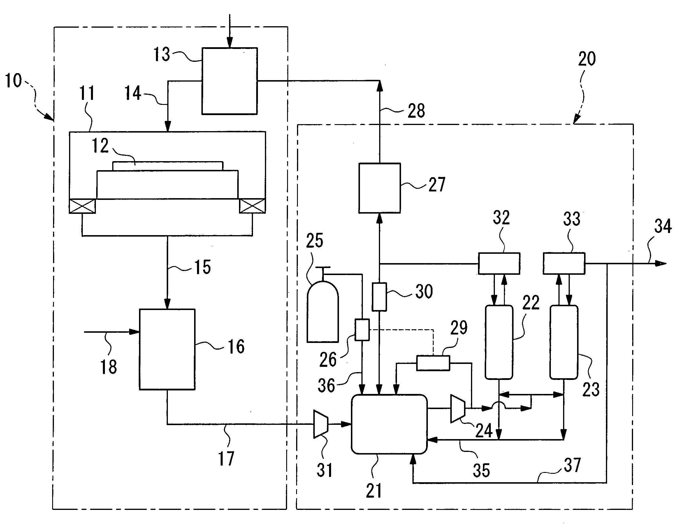
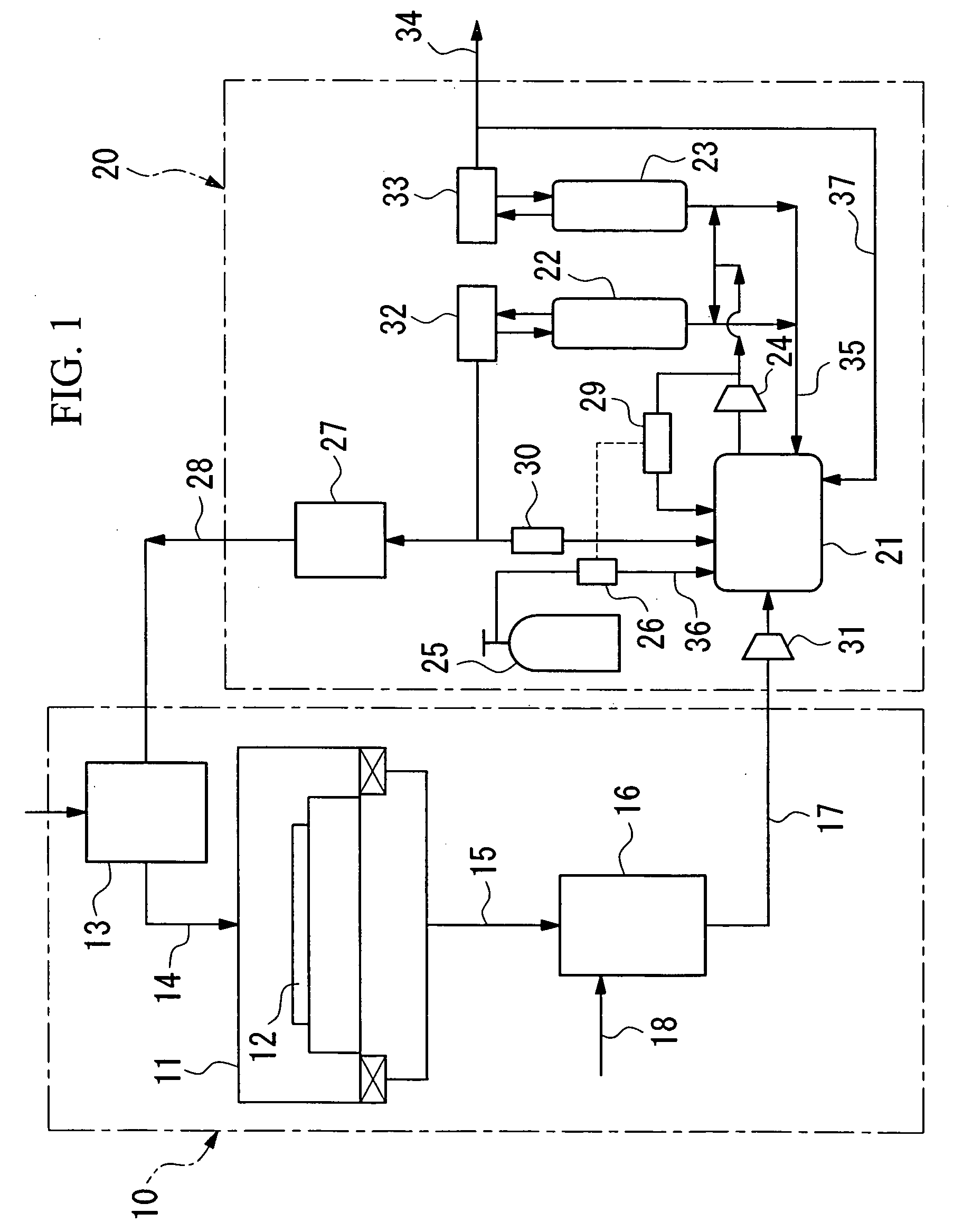
[0041] In a gas supplying system having a structure shown in FIG. 1, 6.5 kg of Zeolite 4A was filled in the first adsorption tower 22 having an inner diameter of 156 mm and a filling height of 500 mm, and 2 kg of activated carbon was filled in the second adsorption tower 23 having an inner diameter of 92 mm and a filling height of 700 mm. A volume variable tank having a maximum volume of 100 L and a minimum volume of 20 L was used as the exhaust gas storage tank 21. Exhaust gas was introduced into the gas supplying device at a rate of 1 L / min for both nitrogen gas and krypton. The gas introduced into the adsorption tower was compressed to about 0.4 MPa using the compressor 24, and was introduced into each of the adsorption towers at a flow rate of about 22 L / min. A separation operation based on the PSA method was carried out at a process switching period of 200 seconds. The flow rate of the first adsorption tower outlet gas (krypton) and the second adsorption tower outlet gas (nitro...
example 2
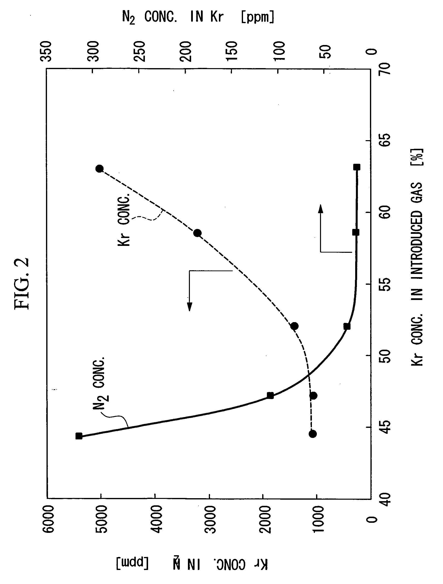
[0043] The flow rate and composition of the exhaust gas introduced into the gas supplying system were varied using the same gas supplying system as in Example 1. First, after exhaust gas with a flow rate of nitrogen of 1 μmin and krypton of 350 cc / min was introduced and stored in the exhaust gas storage tank 21, it was introduced into the adsorption tower in the same manner as described above and a recovery operation for krypton was performed. At that time, the flow rate of krypton in the first adsorption tower outlet gas was about 350 cc / min and the ratio of krypton in the gas introduced into the adsorption tower was stable at about 49%.
[0044] After maintaining this state for about 5000 seconds, while maintaining the flow of nitrogen gas at 1 L / min, krypton was supplied for twenty minutes at a flow rate of 350 cc / min and then the supply of krypton was stopped for 10 minutes. This cycle of supplying krypton was repeated for nine times. After a time delay of about 600 seconds, the f...
example 3
[0045] The stability over a long period was confirmed using the same gas supplying system as in Example 1. The inside volume of the krypton cylinder 25 was 3.4 L, and 680 L (at atmospheric pressure) of krypton was filled therein. The flow controller 26 was operated to replenish krypton so that the ratio of krypton in the gas introduced into the adsorption tower measured by the component detector 29 became 55%. After about 1000 hours of continuous operation, the amount of consumed krypton was measured based on the decrease of pressure inside the krypton cylinder 25 and it was found to be about 123 L (converted to atmospheric pressure). Since the actual annual operation time in hours of the plasma oxidation device 10, which was calculated based on the average rate of operation, is about 5000 minutes, it is understood, by combining the above-mentioned gas supplying devices, that it is not necessary to replace the krypton cylinder for one year if a krypton cylinder having a volume of 3....
PUM
| Property | Measurement | Unit |
|---|---|---|
| Flow rate | aaaaa | aaaaa |
| Ratio | aaaaa | aaaaa |
Abstract
Description
Claims
Application Information
 - R&D
- Intellectual Property
- Life Sciences
- Materials
- Tech Scout
- Unparalleled Data Quality
- Higher Quality Content
- 60% Fewer Hallucinations
Browse by: Latest US Patents, China's latest patents, Technical Efficacy Thesaurus, Application Domain, Technology Topic, Popular Technical Reports.
© 2025 PatSnap. All rights reserved.Legal|Privacy policy|Modern Slavery Act Transparency Statement|Sitemap|About US| Contact US: help@patsnap.com


