Packaging apparatus and method

a technology of packaging apparatus and method, applied in the field of packaging, can solve the problems of product damage during shipping, extreme cost associated with the molds to create the eps insulation, and product damage during shipping

Inactive Publication Date: 2005-05-26
CANTARPOLYAIR CORP
View PDF8 Cites 76 Cited by
  • Summary
  • Abstract
  • Description
  • Claims
  • Application Information

AI Technical Summary

Benefits of technology

[0033] According to another aspect of the present invention, a method of overwrapping products to protect the products is provided. The method comprises providing a length of tubing, the tubing having an inner surface and an outer surface, the inner surface defining a cavity, the tubing further having a first end and a second end, inserting the product into the cavity of the tubing, and sealing the first and second ends of the tubing, respectively, to secure the product within the cavity of the tubing.

Problems solved by technology

Often, damage to products occurs during shipping.
Regardless of the type of shipment (i.e., water, air, road or rail), products may be subjected to physical impact, dropping, crushing, tearing, breaking, rough handling, puncturing or collision at any time.
One significant downside to EPS packaging is the extreme cost associated with the molds to create the EPS insulation.
While very expensive, this tooling has a somewhat limited production life.
Further, the machinery for molding EPS is very expensive and thus is a major factor in the cost of such protective packaging.
Further, requirements for determining the means for packaging a product includes the cost and time to complete the process.
Such a process, however, results in excess waste of the over-wrapping product and strapping material, thereby increasing cost.
Furthermore, such a process is slow and often does not accomplish the desired result because of inherent deficiencies.
Most of these materials and devices, however, are not readily adaptable to varying sizes and shapes of product.
Additionally many of these materials and devices have performance and cost deficiencies.

Method used


Image

  • Packaging apparatus and method
  • Packaging apparatus and method
  • Packaging apparatus and method

Examples


Embodiment Construction

[0051] While this invention is susceptible of embodiments in many different forms, there is shown in the drawings and will herein be described in detail preferred embodiments of the invention with the understanding that the present disclosure is to be considered as an exemplification of the principles of the invention and is not intended to limit the broad aspect of the invention to the embodiments illustrated.

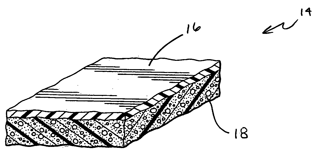
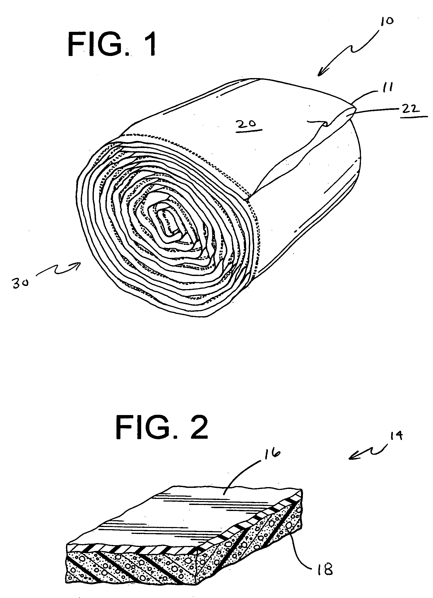
[0052] Referring now in detail to the FIGS., and initially to FIG. 1, there is shown a covering 10 utilized as a protective overwrapping 10 for products during various steps in the material handling process of the products. As explained above, for purposes of this disclosure, the term “material handling” is intended to refer to any or all of the processes and factors relevant to the staging, organizing, storing, locating, loading, moving, shipping, unloading, wrapping, tracking, protecting and generally the overall safety and preservation of the products. In a preferred embod...


PUM

PropertyMeasurementUnit
temperaturesaaaaaaaaaa
heataaaaaaaaaa
densityaaaaaaaaaa

Abstract

A covering 10 for protecting an item that is placed within the covering 10 is provided. The covering 10 includes a substantially continuous tubing 11 having an inner surface 22, an outer surface 20, and a first opening 32 providing access to a cavity 34 of the continuous tubing 11. The continuous tubing 11 is adapted to have items to be protected inserted into cavity 34 of the tubing 11 through the first opening 32. A method for creating the protective covering 10 is also provided. In one preferred embodiment of the invention the method includes sealing an automobile bumper in the tubing 11 for protection of the bumper during material handling thereof.

Description

TECHNICAL FIELD [0001] The present invention relates generally to the field of packaging, and more specifically to an apparatus and method for packaging items for protection during shipment. BACKGROUND OF THE INVENTION [0002] Consumers demand that products they purchase be free of surface marks or any other physical damage. Often, damage to products occurs during shipping. Regardless of the type of shipment (i.e., water, air, road or rail), products may be subjected to physical impact, dropping, crushing, tearing, breaking, rough handling, puncturing or collision at any time. There are a variety of methods and devices which are commonly used for insulating and protecting products and components from physical damage during handling, shipping, transportation, etc. [0003] Included in those devices which are utilized to isolate and protect products from damage are insulating materials and insulating devices. Examples of insulating devices include special containers, such as boxes, envel...

Claims


Application Information

Patent Timeline
Patent Type & Authority Applications(United States)
IPC IPC(8): B65D75/06B65D85/68
CPCB65D85/68B65D75/06
Inventor VERSHUM, RAYMOND G.FOSTER, DALE L.OSBORNE, JOSEPH SPENCER III
Owner CANTARPOLYAIR CORP
Why Eureka
Try Eureka