Flow sensing apparatus

a flow sensing and flow control technology, applied in the direction of instruments, separation processes, filtration separation, etc., can solve the problems of inability to deliver nano-scale hplc flow rates with reliability and accuracy, unpredictable split ratio variation, and inability to control flow through the chromatographic column, etc., to achieve accurate measurement and control of capillary fluid flow, minimize delay, and be readily available

Active Publication Date: 2005-05-26
WATERS TECH CORP
View PDF22 Cites 41 Cited by
  • Summary
  • Abstract
  • Description
  • Claims
  • Application Information

AI Technical Summary

Benefits of technology

[0016] Thermal flow sensors or pressure measuring sensors as described hereinbefore can be used as upstream, waste or operating stream flow sensors with good accuracy and precision. When the flow sensor is used in the operating path, in order to obtain acceptable accuracy and precision, a sensor of different scaling from the main flow sensor is used (i.e. for a pressure-based flow sensor, a less permeable restrictor is used to produce a measurable pressure drop for nano-scale flow rates, for a thermal-based flow sensor, the sensing elements' thermal mass is scaled to allow measurement of nano-scale mass flow rates).
[0026] Illustrative embodiments of the present invention feature a method for measuring and controlling nano-scale flow rates in a capillary system by measuring liquid flow in the high flow rate range. In applications wherein nanoscale flow sensors are not available or are prohibitively expensive, for example, sensors that are precise, accurate and readily available are configured in the high volume stream and used to monitor and control the related nano-scale flow rate in the operating stream. A method for accurately measuring and controlling capillary fluid flows in the nL / min (nano-scale) range is provided that is not sensitive to changes in the fluid composition over time. Accordingly, the present invention is particularly useful to measure and control the operating stream to an LC (liquid chromatography) column in a HPLC system.
[0027] The present invention effectively avoids the need to calibrate thermal type sensors according to the thermal conductivity of each liquid being measured. Pressure-type thermal flow sensors may also be used within the accurate operating range of the pressure-type sensors. The present invention substantially eliminates the need to calibrate the pressure type sensors according to the viscosity of each liquid being measured or the changing permeability of the capillary system. Advantageously, the invention also minimizes the delay caused by the large internal volume of pressure-type flow sensors, by positioning the sensors in an appropriate location, such as outside of the nano-scale flow path. In applications where suitable nano scale flow sensors are not available, embodiments of the present invention provide a method and apparatus for sensing nano scale flow rates with thermal flow sensors within the accurate operating range of the thermal flow sensors.

Problems solved by technology

Plunger displacement pumping systems can not deliver nano-scale HPLC flow rates with reliability and accuracy.
Although it is possible to calculate split restrictor dimensions that should provide a desired split ratio, changes in permeability of either the split restrictor or chromatographic column over time cause unpredictable split ratio variations.
Such variations result in unacceptable flow variations through the chromatographic column.
This creates a great disadvantage in liquid chromatography applications wherein fluid composition varies dramatically over the course of a chromatography run.
The dynamic range of thermal flow sensing is limited by the sensitivity and precision of the temperature measurement instruments.
The upper dynamic range is limited by the dynamic range of the temperature sensors and by the amount of heat that can be added to the flowing liquid.
This creates a great disadvantage in liquid chromatography applications wherein fluid composition varies dramatically over the course of a chromatography run.

Method used


Image

  • Flow sensing apparatus
  • Flow sensing apparatus
  • Flow sensing apparatus

Examples


Embodiment Construction

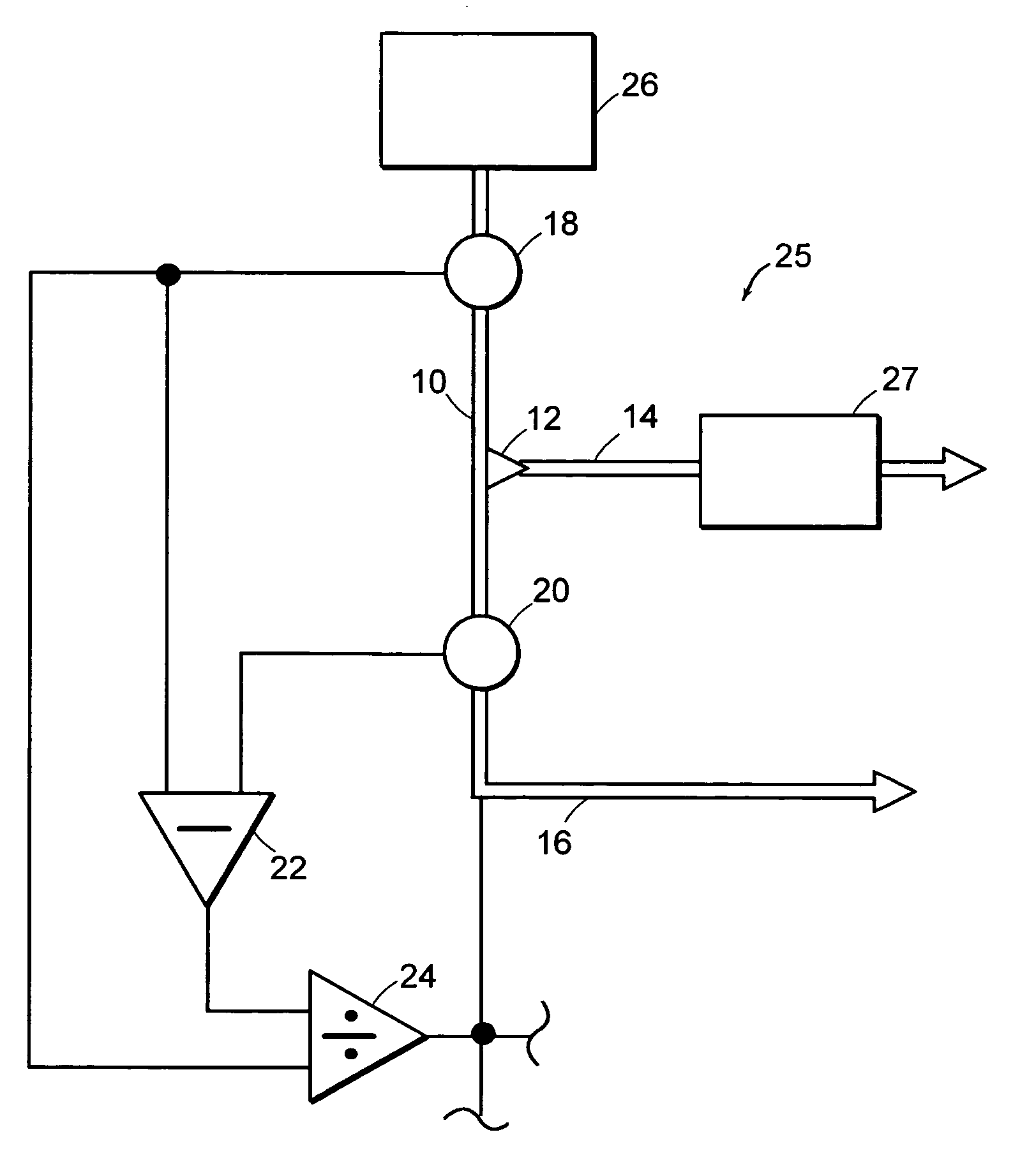
[0039] An illustrative embodiment of a capillary system 25 according to the invention is described generally with reference to FIG. 3. A main flow path 10 is divided by a flow-divider 12 into an operating flow path 14 and a waste flow path 16. A main flow sensor 18 is operatively disposed in the main flow path 10. A waste flow sensor 20 is operatively disposed in the waste flow path 16. Outputs from both the main flow sensor 18 and the waste flow sensor 20 are connected to the input of a subtractor 22 for communicating volumetric flow rate signals to the subtractor 22. Outputs from both the main flow sensor 18 and the subtractor 22 are connected to inputs of a divider 24 for communicating the main volumetric flow rate signal and a difference signal to the divider 24. The output of the divider 24 can be used, for example as described hereinafter to control flow rate in an operating stream.

[0040] In an illustrative embodiment depicted in FIG. 4, the capillary system 25 is a high pres...


PUM

PropertyMeasurementUnit
flow ratesaaaaaaaaaa
pressure path flow ratesaaaaaaaaaa

Abstract

A method and apparatus for monitoring and controlling the nano-scale flow rate of fluid in the operating flow path of a HPLC system. A first flow sensor is disposed in a first flow path between a first flow-divider and a fluidic tee. A second flow sensor is disposed in a second flow path between a second flow-divider and the fluidic tee. A first recycle flow restrictor is disposed in the first recycle flow path in fluid communication with the first flow-divider. A second recycle flow restrictor is disposed in the second The permeability of each recycle flow restrictor can be selected to produce a desired flow rate with each respective flow path. The output signals of the first and second flow sensors to control output of a pump within each flow path.

Description

RELATED APPLICATIONS [0001] The present application is a Continuation-In-Part of U.S. patent application Ser. No. 10 / 723,973 filed Nov. 26, 2003, entitled Flow Sensing Apparatus Used To Monitor / Provide Feedback To A Split Flow Pumping System, which is incorporated herein in its entirety.FIELD OF THE INVENTION [0002] The present invention relates to a flow sensing method and apparatus and more particularly to a flow sensing method and apparatus used to monitor and provide feedback to a split-flow pumping system which enables the delivery of stable flow to a nano-scale chromatographic system using a micro-scale or normal scale chromatographic pump. BACKGROUND OF THE INVENTION [0003] Traditional plunger displacement pumping systems have been successful in delivering stable, accurate flows in the normal-scale and micro-scale high performance liquid chromatography (HPLC) regimes. While normal-scale HPLC is performed with mobile phase flow rates of about 0.1-5.0 mL / min and micro-scale HPL...

Claims


Application Information

Patent Timeline
Patent Type & Authority Applications(United States)
IPC IPC(8): G01F1/36G01F1/68G01N30/10G01N30/30G01N30/32
CPCG01F1/363G01F1/68G01N30/10G01N30/30G01N30/32G01N2030/326G01N2030/324G05D11/132B01D15/14
Inventor GERHARDT, GEOFF C.LUONGO, JOSEPH A.
Owner WATERS TECH CORP
Why Eureka
Try Eureka