Gas generator for a sterilizing system
- Summary
- Abstract
- Description
- Claims
- Application Information
AI Technical Summary
Benefits of technology
Problems solved by technology
Method used
Image
Examples
Embodiment Construction
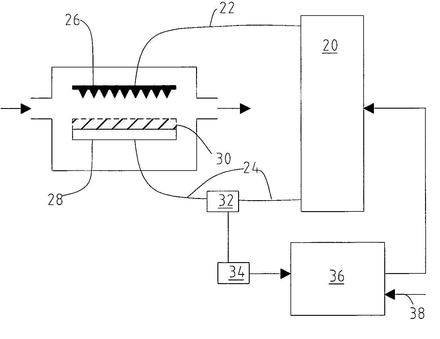
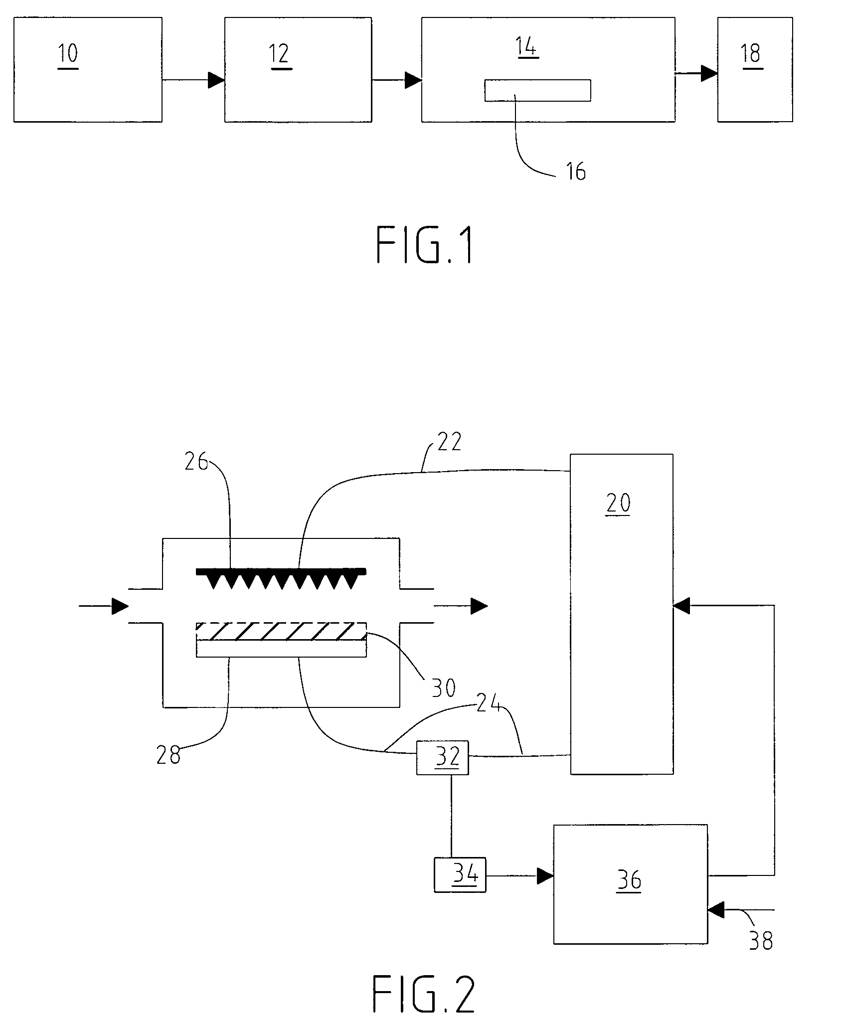
[0025]FIG. 1 shows a schematic diagram of a plasma sterilization system. In such a system, a source of non-biocidal gas 10 injects non-biocidal gas into a plasma generation system 12 which generates a biocidal plasma from the non-biocidal gas and injects the sterilizing biocidal gas formed in this way into a treatment area 14 containing the object or objects to be sterilized 16. The gas emerging from this area is discharged to the exterior, preferably after passing through a system 18 for filtering harmful residues. The treatment area is sealed and subjected to ambient temperature and pressure. The biocidal gas contained in the treatment area must have a relative humidity of more than 50%. This can be achieved either by humidifying the non-biocidal gas during its generation, or directly by injecting a moist gas (advantageously the same non-biocidal gas) into the treatment area. The plasma generation system 12 may or may not be (wholly or partially) separated from the treatment area ...
PUM
| Property | Measurement | Unit |
|---|---|---|
| Decimal reduction time | aaaaa | aaaaa |
| Decimal reduction time | aaaaa | aaaaa |
| Decimal reduction time | aaaaa | aaaaa |
Abstract
Description
Claims
Application Information
 - R&D
- Intellectual Property
- Life Sciences
- Materials
- Tech Scout
- Unparalleled Data Quality
- Higher Quality Content
- 60% Fewer Hallucinations
Browse by: Latest US Patents, China's latest patents, Technical Efficacy Thesaurus, Application Domain, Technology Topic, Popular Technical Reports.
© 2025 PatSnap. All rights reserved.Legal|Privacy policy|Modern Slavery Act Transparency Statement|Sitemap|About US| Contact US: help@patsnap.com


