
Composite stent with inner and outer stent elements and method of using the same

Inactive Publication Date: 2005-05-26
BOSTON SCI SCIMED INC
View PDF85 Cites 98 Cited by
  • Summary
  • Abstract
  • Description
  • Claims
  • Application Information

AI Technical Summary

Problems solved by technology

Removal can be difficult if tissue has grown into the stent, and if the stent is removed forcefully, tissue damage can occur.
One such condition, carcinomas in the esophagus may lead to progressive dysphagia, i.e. difficulty in swallowing, and the inability to swallow liquids in the most severe cases.
While surgical removal of the carcinoma is sometimes effective, the majority of patients have tumors that can not be surgically removed.
These techniques, while often effective, have disadvantages.
Placement of rigid plastic stents is traumatic, and too frequently causes perforation of the esophageal wall.
These prostheses further are subject to migration, obstruction with food or tumor ingrowth, and damage to surrounding cells.
Laser therapy is expensive, typically requiring several treatment sessions.
Submucosal tumors, and certain pulmonary and breast tumors causing dysphagia by esophageal compression, can not be treated by laser therapy.
However, violation of the lumen wall carries the risk of wound contamination, as well as possible fistula formation.
Factors such as cardiac risk, multisystem failure, general debility, malnutrition and infection limit the patient's health and chances of tolerating the radical curative surgical procedure.
Mesh stents are unlikely to lead to pressure necrosis of the esophageal wall.
However, a major complication in both malignant and benign cases is stent / lumen re-occlusion over time.
This makes separation of the stent or a stent cover from surrounding tissue difficult.
Irritation and inflammation of tissue can result from an anchored stent or its cover being removed.
For example, stents covered with ePTFE, such as Precedent, are easily removed after a given time period, such as six months, but may not provide sufficient fixation to prevent the risk of migration during the six month period.

Method used


Image

  • Composite stent with inner and outer stent elements and method of using the same
  • Composite stent with inner and outer stent elements and method of using the same
  • Composite stent with inner and outer stent elements and method of using the same

Examples


Embodiment Construction

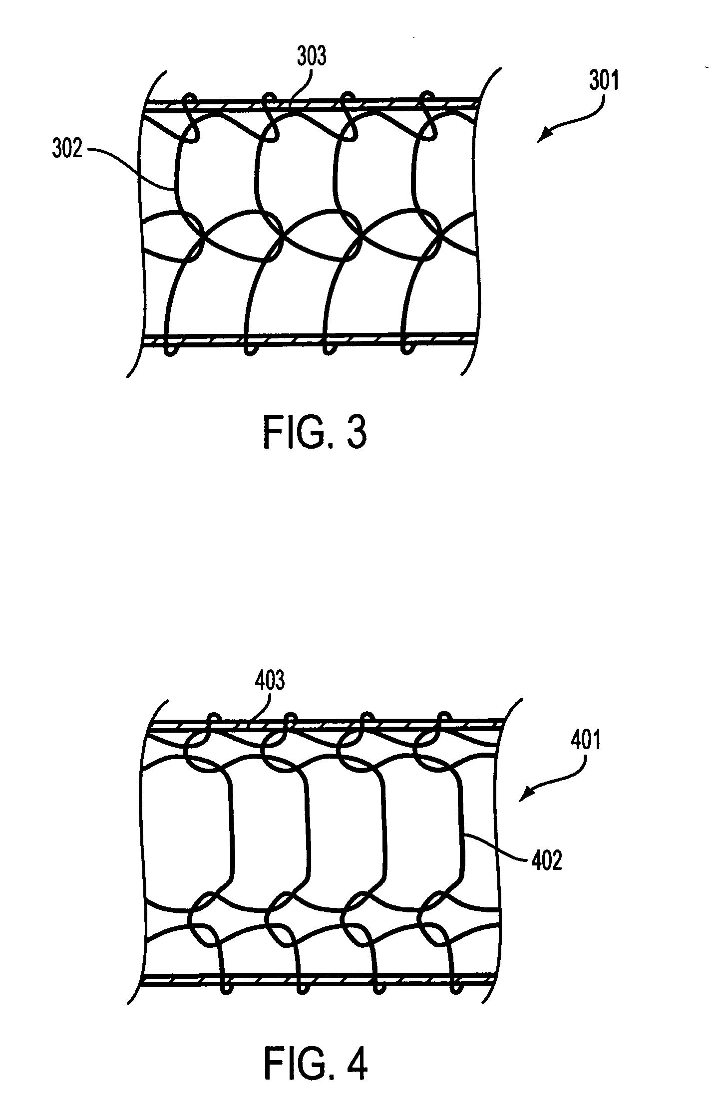
[0041] Referring to FIG. 3, according to an embodiment of the invention, a composite stent 301 includes an outer bioabsorbable mesh or similar stent element 302 affixed to a fully covered inner self-expanding metal stent (SEMS) 303 (only the covering of inner stent in visible). Suitable outer bioabsorbable or biodegradable stents are typically made from a bioabsorbable polymer. Polymer structures typically have a higher potential to creep (i.e., experience permanent deformation and fail to return to an original shape and / or size when released) if held in a constrained condition while in the delivery system. The potential for creep in the outer element may increase with temperature elevation such as in sterilization. The fully covered SEMS 401 will self-expand as shown in FIG. 4 so that the combined structure 401 (covered inner SEMS 403 and bioabsorbable mesh 402) overcomes any loss in recovered diameter. Only the covering of the inner stent is shown in FIG. 4. While some bioabsorbab...


PUM


Abstract

An endoprosthesis comprising a stent, a cover fully covering the stent wherein the cover has variable porosity in the radial direction; and an adhesion layer connecting the stent to the cover. Another aspect of the invention is a method of implanting an endoprosthesis which includes a stent, providing a cover with variable porosity in the radial direction, connecting the stent to the cover with an adhesion layer to form a covered stent, and implanting the covered stent within a body lumen of a patient.

Description

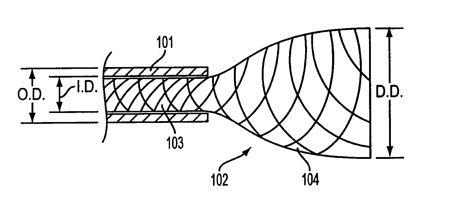
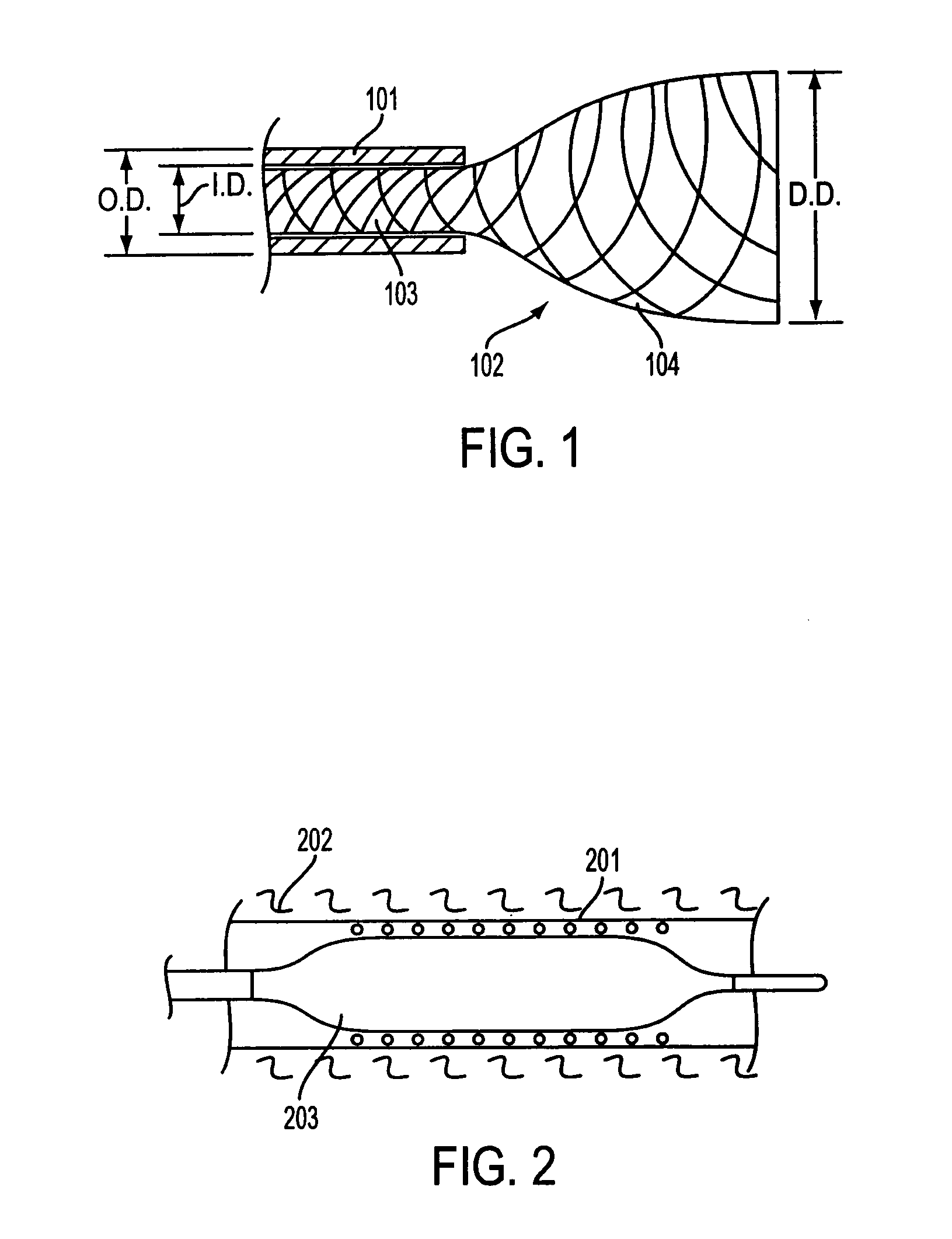
BACKGROUND [0001] 1. Field of the Invention [0002] The present invention relates to body implantable treatment devices, and more particularly to stents and other prostheses intended for fixation in body lumens. [0003] 2. Cross Reference To Related Applications [0004] This application is a continuation-in-part to “Composite Stent With Inner And Outer Stent Elements and Method Of Using The Same”, U.S. patent application Ser. No. 10 / 720,176, by Peter Shank and F. Anthony Headley Jr., filed on Nov. 25, 2003. [0005] Typically, a stent is delivered into position at a treatment site in a compressed state using a delivery device. After the stent is positioned at the treatment site, the delivery device is actuated to release the stent. Following release of the stent, self-expanding stents are allowed to self-expand within the body vessel or lumen. FIG. 1 shows such a configuration including a delivery device in the form of catheter 101 containing a portion 103 of self-expanding stent 102 wit...

Claims


Application Information

Patent Timeline
IPC IPC(8): A61F2/00A61F2/86
CPCA61F2210/0076A61F2220/0041A61F2220/005A61F2/86A61F2/07A61L31/129A61F2/82A61F2220/0066A61L31/146A61F2220/0008B05D1/002A61F2002/075A61F2250/0067A61F2220/0075A61F2/90
Inventor SHANK, PETER J.ZHONG, SHENG-PINGDAO, KINH-LUAN D.HEADLEY, F. ANTHONY JR.
Owner BOSTON SCI SCIMED INC
Learn More