
Decoupling a harmonic signal from a signal path

a signal path and harmonic signal technology, applied in the direction of electronic commutators, electric controllers, dynamo-electric converter control, etc., can solve the problems of harmonic components changing, mapping can take considerable time, and reduce the dynamic performance of estimation blocks

Inactive Publication Date: 2005-05-26
GM GLOBAL TECH OPERATIONS LLC
View PDF6 Cites 20 Cited by
  • Summary
  • Abstract
  • Description
  • Claims
  • Application Information

AI Technical Summary

Benefits of technology

The present invention provides a method and system for decoupling a harmonic signal from an input signal. This is useful in controlling electric motors and other systems. The method involves multiplying the angular position of the input signal by a value representing the harmonic to obtain an angular position multiple. The input signal and a sine or cosine of the angular position multiple are then filtered to obtain a DC cosine or sine signal. These signals are then multiplied by a second value to obtain a second correction signal. The correction signals are then subtracted from the input signal to decouple the harmonic signal. The technical effect of this invention is that it allows for more accurate control and decoupling of harmonic signals from input signals, leading to improved performance and efficiency of electric motors and other systems.

Problems solved by technology

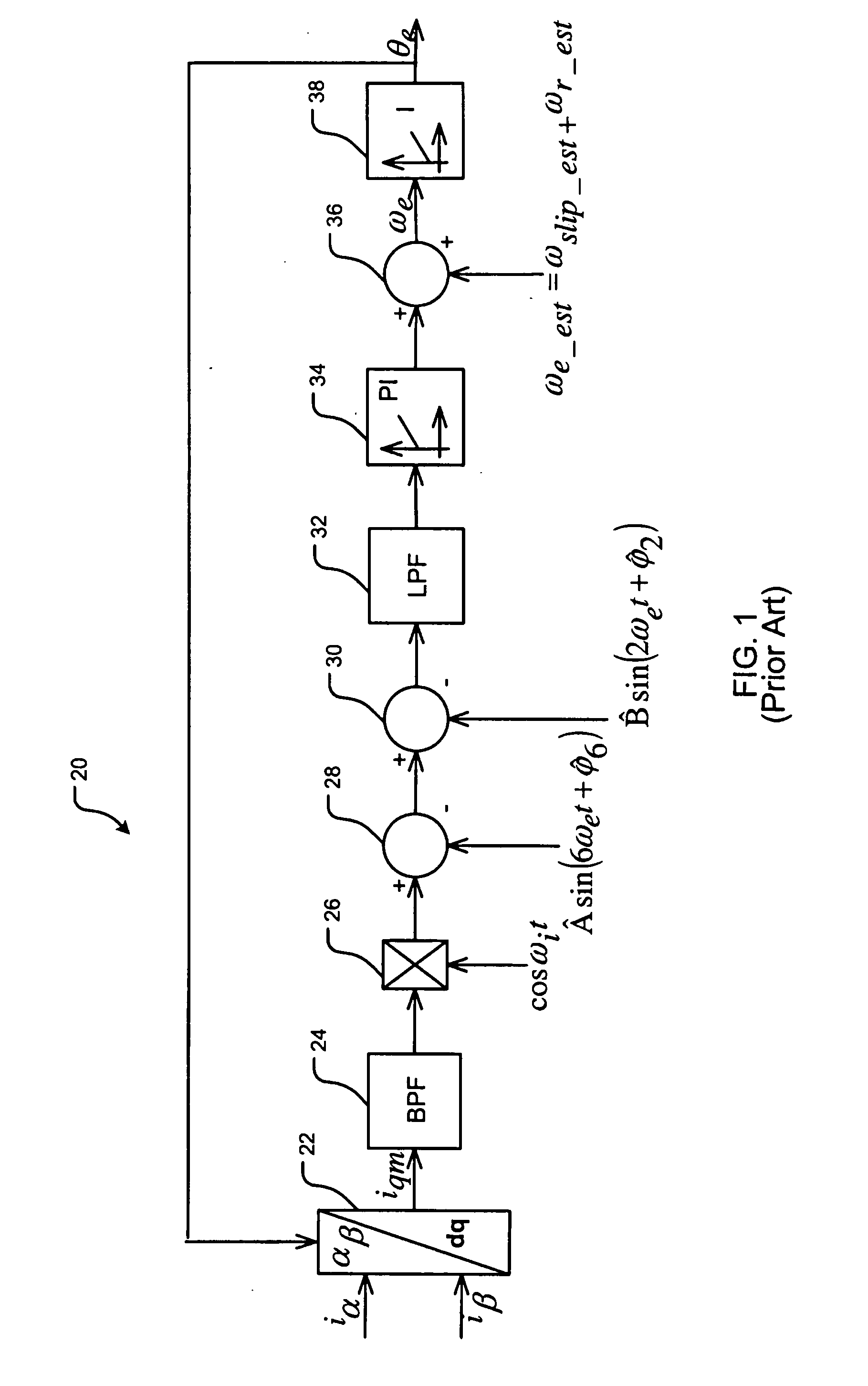
However, if BPF 24 is too selective (i.e., has a high quality factor Q), it can reduce the dynamic performance of the estimation block.
This mapping can take considerable time.
Moreover, harmonic components can change as a function of variables (such as motor temperature and inverter temperature) that are difficult to take into account.
Thus, accuracy of the result can be adversely affected.

Method used


Image

  • Decoupling a harmonic signal from a signal path
  • Decoupling a harmonic signal from a signal path
  • Decoupling a harmonic signal from a signal path

Examples


Embodiment Construction

[0020] The following description of various embodiments is merely exemplary in nature and is in no way intended to limit the invention, its application, or uses. Although embodiments of the present invention are described in connection with induction motors and induction motor control systems, it should be understood that the invention is not so limited. Embodiments are contemplated for use in connection with many different types of electrical and electromechanical circuits and systems wherein it is desired to decouple a harmonic signal from a signal path.

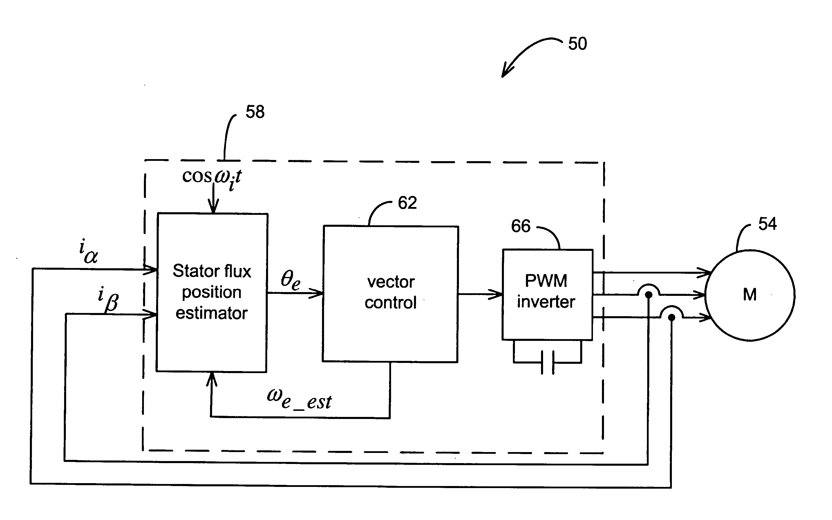
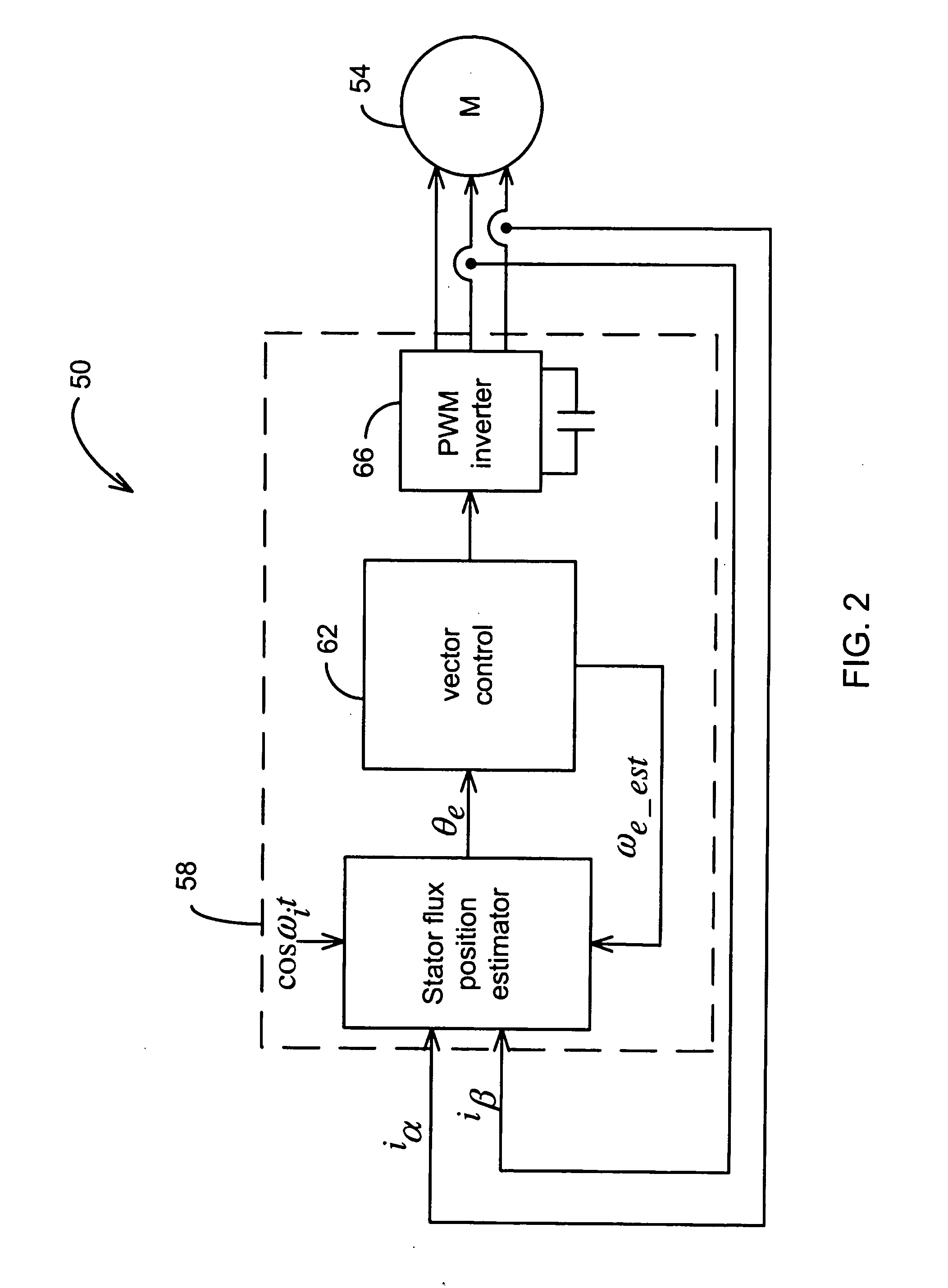
[0021] A motor apparatus according to one embodiment of the present invention is indicated generally in FIG. 2 by reference number 50. A motor 54, for example, an induction motor, is driven via a pulse-width modulation (PWM) controller 58. The controller 58 includes a stator flux position estimator 100 into which is injected a high-frequency signal as further described below. Motor stator input currents ia and iβ are input to the ...


PUM


Abstract

A method for decoupling a harmonic signal from an input signal wherein the harmonic signal is harmonic relative to a signal other than the input signal. An angular position of the other signal is multiplied by a value representing the harmonic to obtain an angular position multiple. A harmonic decoupling block uses the angular position multiple to obtain correction signals representing the harmonic signal, and subtracts the correction signals from the input current to decouple the harmonic signal from the input signal. This method is useful for decoupling unwanted harmonics from currents into which high-frequency signals have been injected for control of electric motors.

Description

FIELD OF THE INVENTION [0001] The present invention relates to decoupling a harmonic signal from a signal path in an electrical or electromechanical circuit, and more particularly to decoupling a harmonic signal from an input signal wherein the harmonic signal is harmonic relative to a signal other than the input signal. BACKGROUND OF THE INVENTION [0002] In an induction motor, a rotor is mounted in a stator and is separated from the stator by an air gap. During operation of the motor, alternating currents supplied to windings of the stator induce currents in windings of the rotor. Due to magnetic material saturation, leakage inductance from the stator tends to be lower in regions in which rotor magnetic flux circulates than in regions in which rotor flux is not present. Because rotor magnetic flux direction is associated with a direct axis (d-axis), quadrature axis (q-axis) leakage inductance is lower than direct axis leakage inductance. [0003] It is known to control the operation ...

Claims


Application Information

Patent Timeline
Patent Type & Authority Applications(United States)
IPC IPC(8): G05B11/36H02P6/18H02P21/14H04B
CPCH02P6/183H02P6/185H02P2207/01H02P2203/11H02P21/146H02P21/18
Inventor STANCU, CONSTANTIN C.HITI, SILVASCHULZ, STEVEN E.PATEL, NITINKUMAR R.
Owner GM GLOBAL TECH OPERATIONS LLC
Learn More