Digital delay-locked loop circuits with hierarchical delay adjustment

Inactive Publication Date: 2005-05-26
ROUND ROCK RES LLC
View PDF24 Cites 18 Cited by
  • Summary
  • Abstract
  • Description
  • Claims
  • Application Information

AI Technical Summary

Benefits of technology

[0012] The use of hierarchical delay adjustment advantageously allows the delay-lo

Problems solved by technology

The minimum delay adjustment for the variable delay line and phase mixer is limited by the amount of circuitry dedicated to providing the minimum delay adjus

Method used


Image

  • Digital delay-locked loop circuits with hierarchical delay adjustment
  • Digital delay-locked loop circuits with hierarchical delay adjustment
  • Digital delay-locked loop circuits with hierarchical delay adjustment

Examples


Embodiment Construction

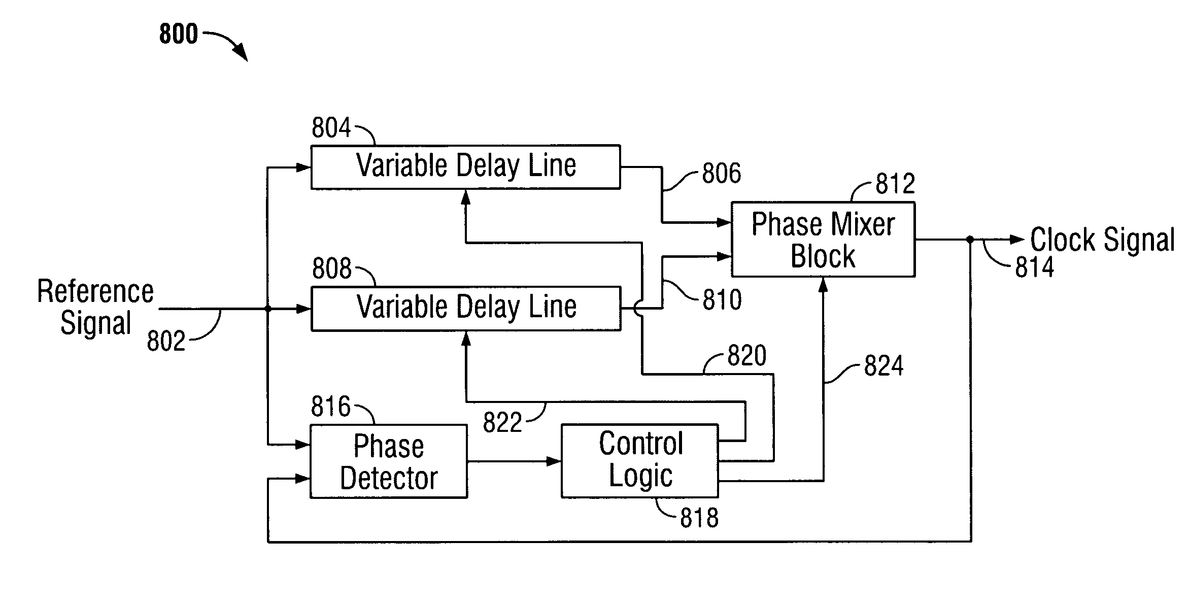
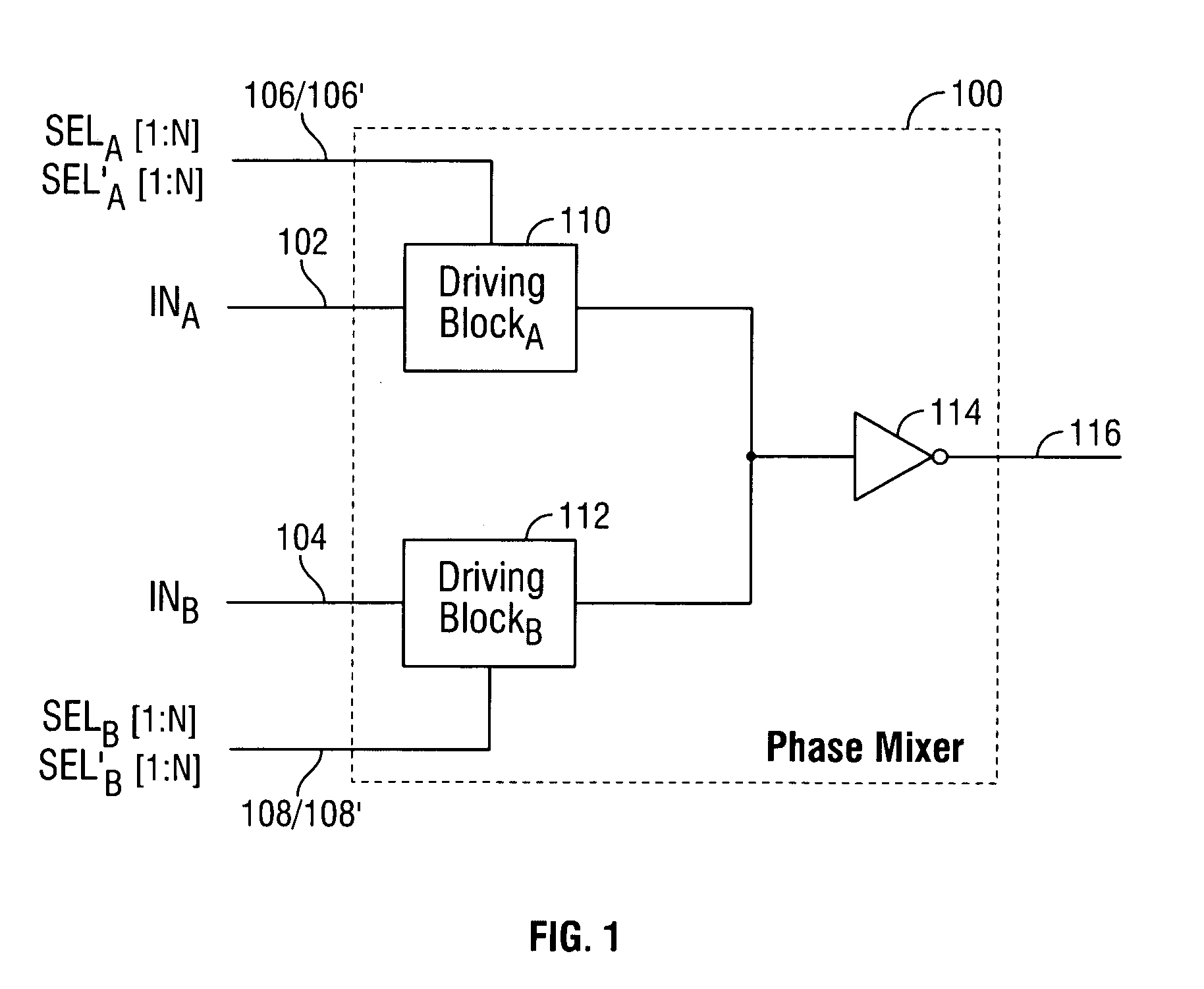
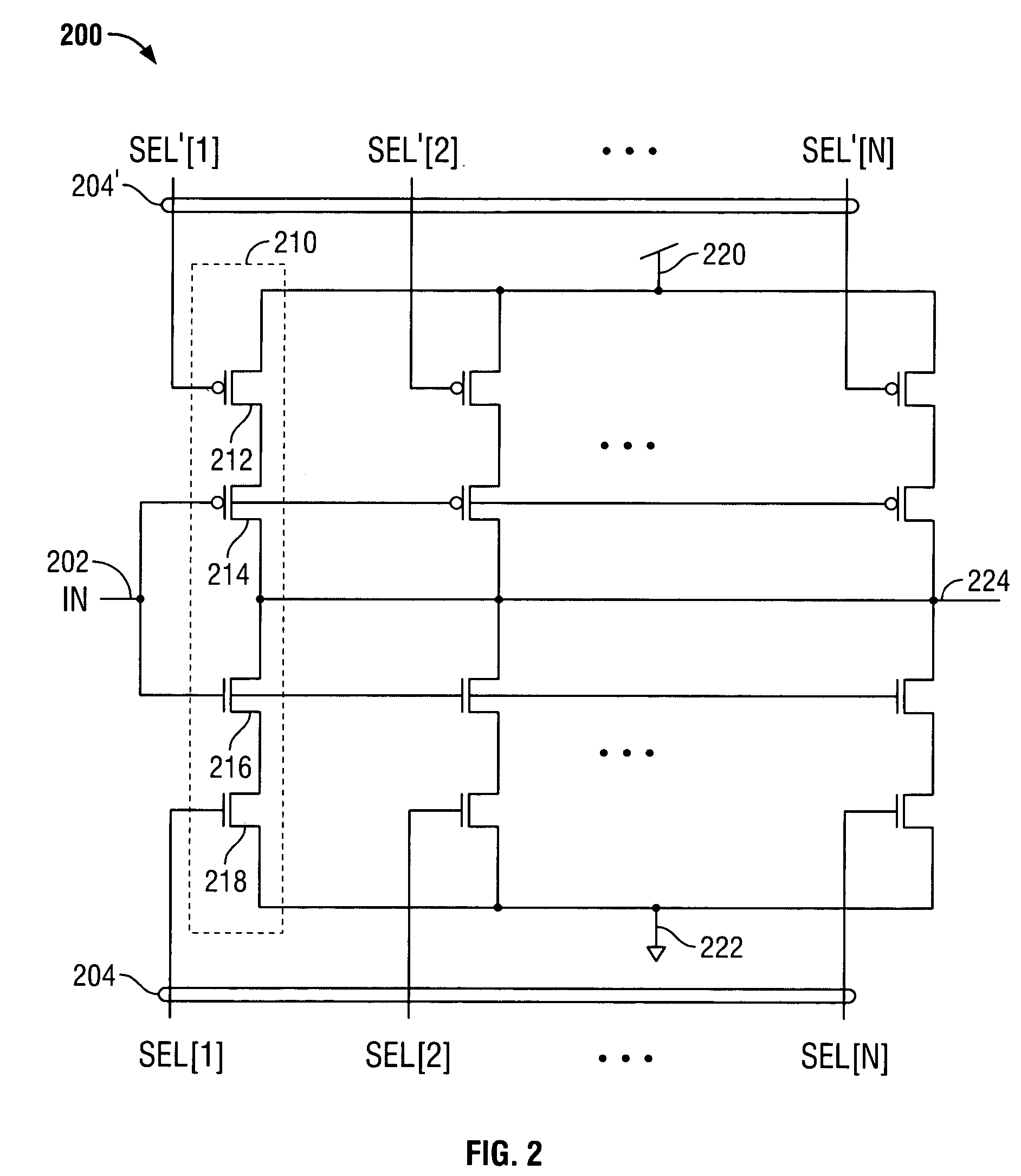
[0023] The invention provides a digital delay-locked loop circuit with hierarchical delay adjustment. FIG. 1 is a block diagram of one embodiment of a digital phase mixer in accordance with the invention. Phase mixer 100 receives two input signals 102 and 104 and two select signals 106 and 108, and outputs a signal 116 having a phase between the phases of input signals 102 and 104. Input signals 102 and 104 can be clock signals, data signals, control signals, or other types of signals. Input signals 102 and 104 can have phases (e.g., 0°, 10°, 36°, 45°, 90°) that are any suitable degrees apart. (Although the invention is described herein primarily in the context of phase (e.g., with units of degrees or radians), the invention may also be described in the context of time (e.g., input signals 102 and 104 can be 100 picoseconds apart)). For more optimal performance, the maximum phase difference between input signals 102 and 104 is preferably less than about two to three times the total ...


PUM


Abstract

Fine tuned signal phase adjustments are provided by multiple cascaded phase mixers. Each phase mixer outputs a signal having a phase between the phases of its two input signals. With each subsequent stage of phase mixers, the signals generated by the phase mixers have a smaller phase difference, thereby providing finer delay adjustments. Multiple stages of phase mixers can be provided in digital delay-locked loop circuitry to provide additional hierarchical delay adjustment.

Description

BACKGROUND OF THE INVENTION [0001] This invention relates to digital delay-locked loop (DLL) circuits. More particularly, this invention relates to digital delay-locked loop circuits with hierarchical delay adjustment. [0002] Digital delay-locked loop circuits typically generate a clock signal based on a periodic reference signal (e.g., from an oscillator) that maintains a specific phase relationship with that reference signal. Digital delay-locked loop circuits are often used, for example, in high-speed clocked memories such as synchronous dynamic random access memories (SDRAMs). [0003] A digital delay-locked loop circuit generally includes a variable delay line, a phase mixer, a phase detector, and control logic. The variable delay line includes delay units that are used to delay the reference signal by a predetermined time period (i.e., phase). The number of delay units indicate the number of possible unit delays (i.e., tUDs) that can be generated by the variable delay line. For ...

Claims


Application Information

Patent Timeline
IPC IPC(8): H03L7/081
CPCH03L7/0814H03L7/0816
Inventor LEE, SEONG-HOON
Owner ROUND ROCK RES LLC
Why Eureka
Try Eureka