Digital phase mixers with enhanced speed

a phase mixer and digital signal technology, applied in the field of digital signal phase mixers, can solve the problems of affecting the high speed performance of a phase mixer, increasing the desired phase of the output signal, etc., and achieve the effect of reducing the propagation delay

Inactive Publication Date: 2005-05-26
ROUND ROCK RES LLC
View PDF23 Cites 7 Cited by
  • Summary
  • Abstract
  • Description
  • Claims
  • Application Information

AI Technical Summary

Benefits of technology

[0005] It is an object of this invention to provide digital phase mixers with reduced propagation delay.

Problems solved by technology

Generation of the output signal, typically results in a propagation delay, which increases the desired phase of the output signal.
This non-zero propagation delay can impede the high speed performance of a phase mixer.

Method used


Image

  • Digital phase mixers with enhanced speed
  • Digital phase mixers with enhanced speed
  • Digital phase mixers with enhanced speed

Examples


Embodiment Construction

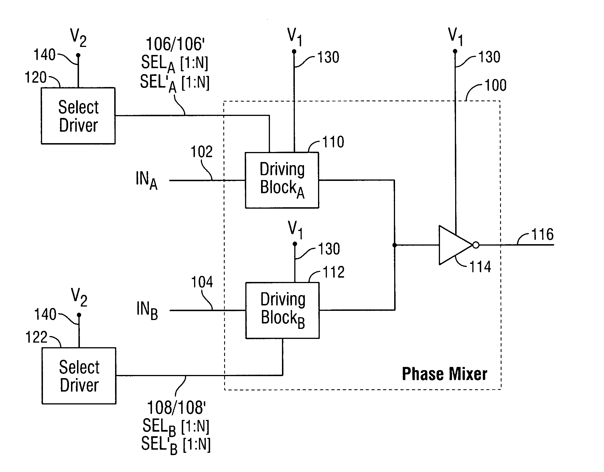
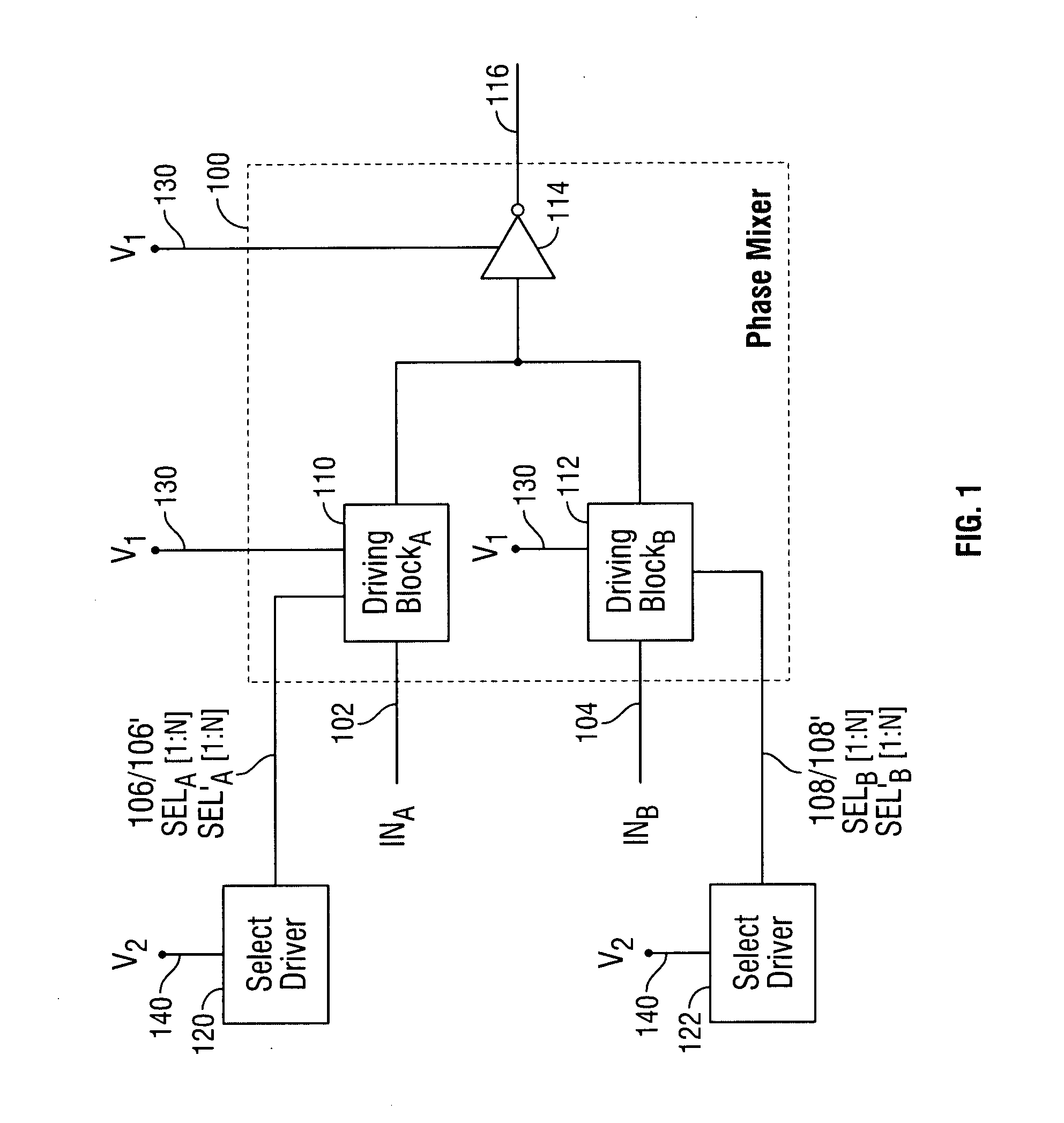
[0016] The invention provides digital phase mixers with enhanced speed. FIG. 1 is a block diagram of one embodiment of a digital phase mixer in accordance with the invention. Phase mixer 100 receives two input signals 102 and 104 and two select signals 106 and 108, and outputs a signal 116 having a phase between the phases of input signals 102 and 104. Input signals 102 and 104 can be clock signals, data signals, control signals, or other types of signals. Input signals 102 and 104 can have phases (e.g., 0°, 10°, 36°, 45°, 90°) that are any suitable degrees apart. (Although the invention is described herein primarily in the context of phase (e.g., with units of degrees or radians), the invention may also be described in the context of time (e.g., input signals 102 and 104 can be 100 picoseconds apart)). For more optimal performance, the maximum phase difference between input signals 102 and 104 is preferably less than about two to three times the total propagation delay time of phas...


PUM


Abstract

Digital phase mixers with enhanced speed are provided. A phase mixer generates a signal having a phase between the phases of two input signals based on select signals. The propagation delay of the output signal is reduced by using a first voltage source to drive the input signals and the output signal and a second voltage source, having a higher voltage than the first voltage source, to drive the select signals. The higher voltage source reduces the impedance of each transistor driven by the select signals, thus reducing the propagation delay at the output of the phase mixer. For a non-differential digital phase mixer, the propagation delay is reduced in the rising edges of the output signal. For a differential digital phase mixer, the propagation delay is reduced in the rising and falling edges of the output signal.

Description

BACKGROUND OF THE INVENTION [0001] This invention relates to digital signal phase mixers. More particularly, this invention relates to digital phase mixers with enhanced speed. [0002] A phase mixer typically receives two input signals and outputs a signal having a phase between the phases of the two input signals. Select signals can be used to determine the phase of the output signal. The number of bits in the select signals can indicate the number of possible intermediate phases, equally-spaced apart, that can be generated by the phase mixer. For example, two signals having a respective phase of 45° and 90° can be input to a phase mixer, which can then output a signal having a phase between 45° and 90°. If the select signals each have nine bits, the phase mixer can generate an output signal having one of eight possible intermediate phases (e.g., 50°, 55°, 60°, 65°, 70°, 75°, 80°, and 85°). [0003] One voltage source typically drives the input signals, the select signals, and the out...

Claims


Application Information

Patent Timeline
Patent Type & Authority Applications(United States)
IPC IPC(8): G06F7/44G06G7/12H03K5/00H03K5/13H03K5/153
CPCH03K5/13H03K2005/00065H03K5/153
Inventor LEE, SEONG-HOON
Owner ROUND ROCK RES LLC
Why Eureka
Try Eureka