
Virtual pan/tilt camera system and method for vehicles

a camera system and virtual technology, applied in the field of virtual pan/tilt camera system and vehicle camera system, can solve the problems of difficult automatic navigation of ground vehicles, inability to tell whether it is surmountable, and obstacles such as trees, rubble, and other objects

Active Publication Date: 2005-05-26
THE BOEING CO
View PDF16 Cites 22 Cited by
  • Summary
  • Abstract
  • Description
  • Claims
  • Application Information

AI Technical Summary

Benefits of technology

[0008] In accordance with this invention the problems associated with the use of a pan / tilt camera with present ANS technology in an MGV are eliminated by eliminating the pan / tilt cameras on the vehicle and replacing them with a plurality of video infrared cameras. These video / IR cameras are normally included in an MGV to give the vehicle crew a view of the horizon in all directions. Each of the cameras is mounted in a fixed orientation on the vehicle and covers a selected angular range of lateral view, preferably so that every point on the horizon is viewed by two different cameras such that the cameras' fields of view overlap enabling every point on the horizon to be viewed even when a camera is disabled.
[0011] Thus, the present invention eliminates the need for pan / tilt cameras and the disadvantages associated with their use on MGVS, by using a plurality of fixed cameras already included on modern MGVS, each camera covering a selected angular range of lateral view with the imagery from the cameras stitched together to produce a single, seamless panoramic view as may be selected by a crew member. With the present invention, the MGV does not suffer penalties to its radar and infrared signatures as would occur with the use of pan / tilt cameras and their associated mounts. Moreover, the present invention may be used with present ANS technology thereby eliminating the substantial costs that would be associated with developing a new type of ANS. The present invention reduces weight and power requirements as compared to the use of pan / tilt cameras.

Problems solved by technology

The autonomous navigation of ground vehicles is particularly difficult.
For example, there may be obstacles such as trees, brush, rubble, boulders, and other objects that do not appear on the digital map.
From a distance, the ANS can identify that a particular object is present, but may not be able to tell whether it is surmountable, i.e., whether the vehicle can travel over the object.
However, problems occur with the use of ANSs on manned ground vehicles (MGVs).
However, the use of a pan / tilt camera with an MGV presents problems not associated with the use of such a camera with a UGV.
One such problem is that the pan / tilt camera increases vehicle weight and power needs which is of particular concern for MGVs where weight and power are severely constrained.
Another problem is that the pan / tilt mount for the camera is difficult to hide from radar and infrared sensors, thereby compromising the low-observable characteristics needed for military vehicles to survive on the modern battlefield.

Method used


Image

  • Virtual pan/tilt camera system and method for vehicles
  • Virtual pan/tilt camera system and method for vehicles
  • Virtual pan/tilt camera system and method for vehicles

Examples


Embodiment Construction

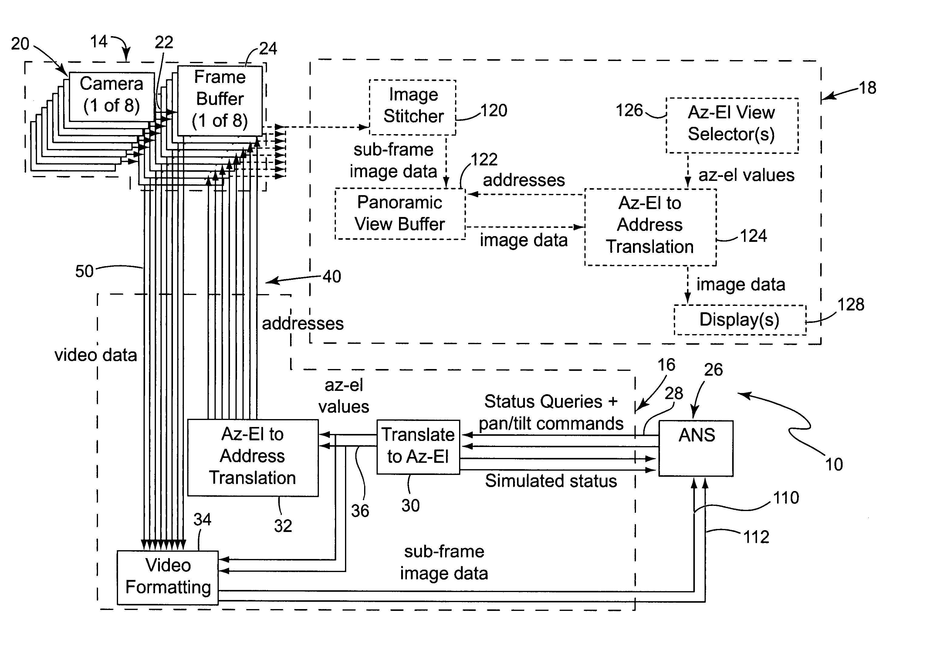
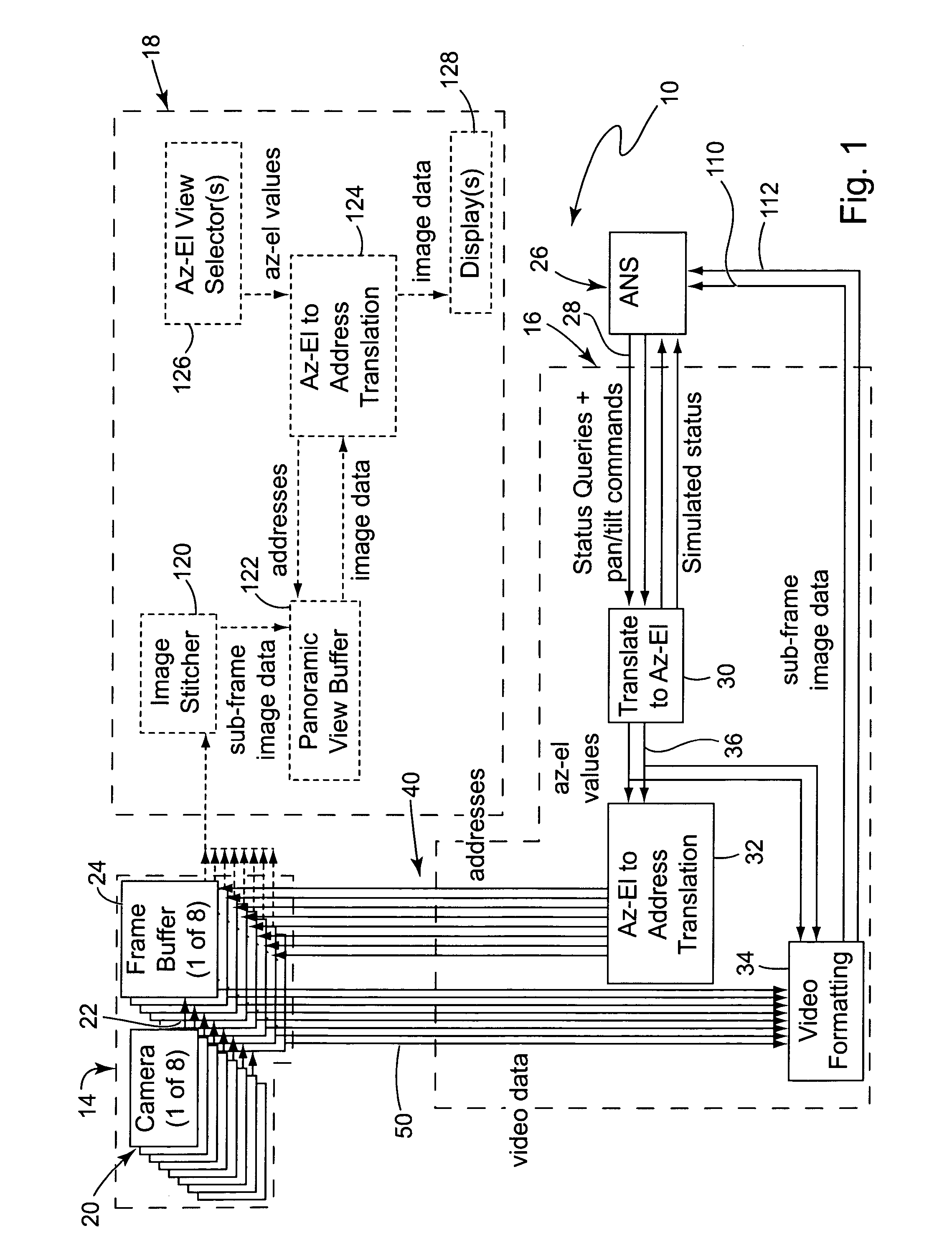
[0017] With reference to the drawings, there is shown a preferred embodiment of a virtual pan / tilt camera system 10 in accordance with the present invention for use with a manned ground combat vehicle 12 as illustrated in FIG. 3. The system generally comprises a fixed camera video data input 14, a reformatting network section 16, and a display system section 18. The fixed camera video data input 14 further comprises a plurality of video cameras 20, each of which is mounted in a fixed position on the vehicle 12. In this embodiment eight such cameras are shown, but it is to be understood that a fewer or greater number of cameras may be used. A suitable camera is the Hitachi HV-C20 or the Sony DXC 9000. Each camera outputs video data 22 representing the images viewed by that camera to a frame buffer 24, there being eight such frame buffers, one for each video camera. Each frame buffer stores at addresses within the buffer the video data it receives from its respective camera.

[0018] An...


PUM


Abstract

The present invention is directed to a virtual pan / tilt camera system and method for use with vehicles, and particularly ground vehicles (MGVs). The invention utilizes autonomous navigation systems (ANSs) used with pan / tilt cameras, but eliminates the pan / tilt cameras substituting a plurality of video cameras. Each video camera is mounted in a fixed orientation on the vehicle and covers a selected angular range of lateral view. Commands from the ANS are mapped to selected addresses where the video data from the video cameras are stored, and appropriately transformed data from the selected addresses are input to the ANS. Computers and software in the MGV receive video data from the cameras and stitch the imagery together into a single panoramic view. Video data from cameras with overlapping fields of view are used to simulate the view of stereo cameras.

Description

STATEMENT REGARDING FEDERALLY SPONSORED RESEARCH OR DEVELOPMENT [0001] This invention was developed in the course of work under U.S. government contract MDA972-02-9-0005. The U.S. government may possess certain rights in the invention.BACKGROUND OF THE INVENTION [0002] This invention is directed to a camera system for vehicles for use with autonomous navigation systems (ANSs), and more particularly to a virtual pan / tilt camera system and method for use with ANSs for ground vehicles, more specifically manned ground combat vehicles. [0003] Unmanned ground vehicles (UGVs) are valuable to the military involved in ground combat. The value of a UGV is increased when it is able to navigate autonomously, as it reduces manpower that must be deployed for a given military operation. Modern ANSs for ground vehicles use machine vision to detect obstacles and navigate paths around the obstacles. Current ANSs use pan / tilt stereo cameras on the outside of the UGV so that the ANS computer can get a ...

Claims


Application Information

Patent Timeline
IPC IPC(8): H04N7/18
CPCH04N7/185H04N7/181H04N7/18
Inventor TILLOTSON, BRIAN J.
Owner THE BOEING CO
Learn More