Integrated variable optical attenuator and related components

a variable optical attenuator and integrated technology, applied in the field of optical devices, can solve the problems of lack of flexibility in system design and cost savings, crosstalk and other deleterious effects can occur,

Inactive Publication Date: 2005-05-26
LIGHTWAVES 2020
View PDF11 Cites 40 Cited by
  • Summary
  • Abstract
  • Description
  • Claims
  • Application Information

AI Technical Summary

Benefits of technology

[0005] The present invention provides for an integrated variable optical attenuator which has a polarization element which continuously varies the state of polarization of polarized light incoming to the integrated variable optical attenuator responsive to a control signal. The integrated variable optical attenuator also has a polarization-sensitive optical isolator fixed with respect to said polarization element so that the amount of polarized light from said polarization element and passing through the polarization-sensitive optical isolator is varied by the state of polarization responsive to the control signal. This combination of polarization element and optical isolator permits integration for a miniaturized device.

Problems solved by technology

Without such adjustments, signal distortion, crosstalk and other deleterious effects can occur.
Element combination does have disadvantages, such as a resulting lack of flexibility in system design and cost savings which are illusory.

Method used


Image

  • Integrated variable optical attenuator and related components
  • Integrated variable optical attenuator and related components
  • Integrated variable optical attenuator and related components

Examples


Embodiment Construction

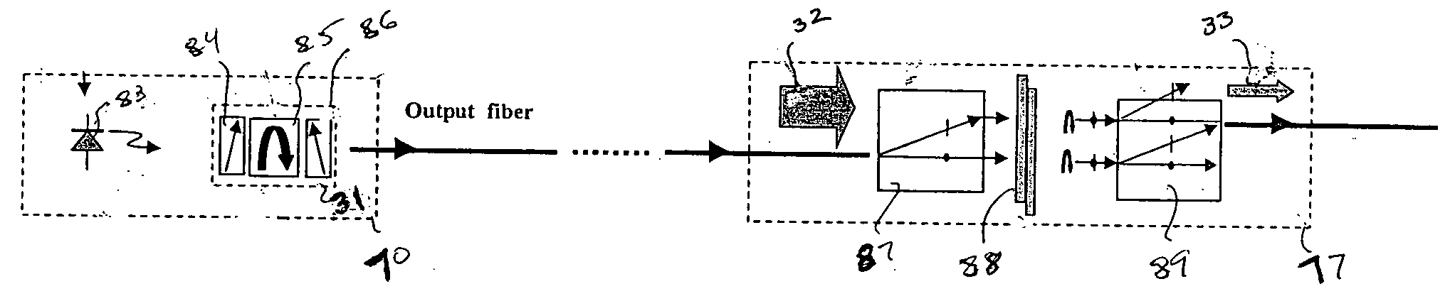
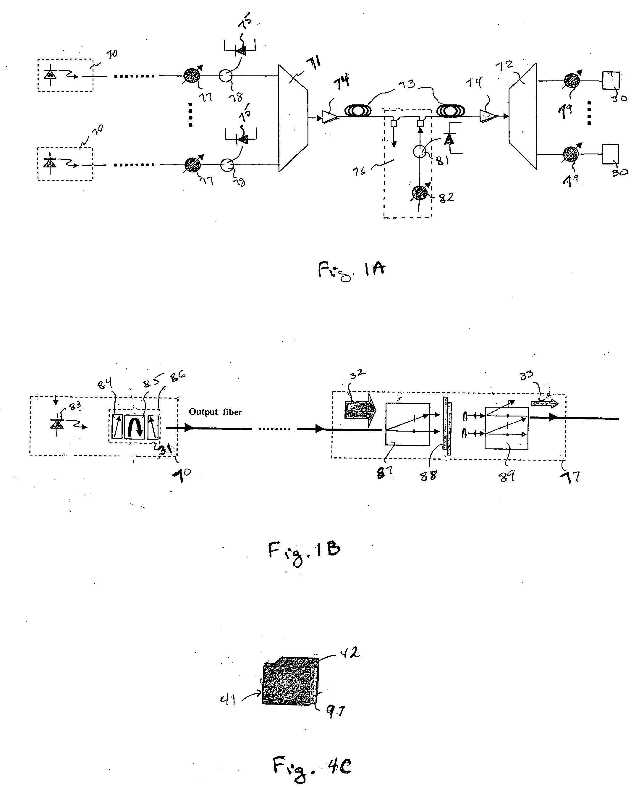
[0014]FIG. 1A is an exemplary optical network by which optical signals from transmitting users are sent through an optical fiber to multiple receiving users. In this representative fiberoptic network, lasers 70 generate optical signals for the transmitting users. The signal strength from each laser 70 is controlled by a VOA 77 responsive to power-monitor readings from a photodiode 75 which is connected to a tap coupler 78 diverting a small fraction of the signal from the output terminal of the VOA 77 to the photodiode 75. The coupler 78 passes most of the VOA output to an input terminal of a multiplexer 71 and the VOAs 77 are adjusted to balance the power of the light signals from the different lasers 70 to the multiplexer 71.

[0015] The output terminal of the multiplexer 71 is connected to an EDFA (Erbium-Doped Fiber Amplifier) 74, or other optical amplifier, which boosts the power of the signals combined by the multiplexer 71 for transmission on an optical fiber 73 to the receivin...


PUM

PropertyMeasurementUnit
insertion lossaaaaaaaaaa
birefringentaaaaaaaaaa

Abstract

A polarization element and a polarization-sensitive optical isolator are integrated to form an integrated VOA. A preferred embodiment uses a liquid crystal cell as the polarization element to which is attached an optical isolator core of a first polarizer, Faraday rotator, and second polarizer. Voltage on the liquid crystal cell electrodes controls the amount of polarized light from the liquid crystal cell passing through the first polarizer and light in the opposite direction is blocked. The integrated VOA can be mounted within a laser device package so that the power of the source laser diode on the output fiber can be controlled and yet the laser diode is protected from light undesirably entering laser device package through the output fiber.

Description

BACKGROUND OF THE INVENTION [0001] The present invention is related to optical devices for fiberoptic systems and networks and, in particular, to variable optical attenuators. [0002] In current fiberoptic systems and networks, variable optical attenuators (VOAs) are ubiquitous. VOAs are typically used for adjusting the strength of signals so that signals are balanced across the network wavelength transmission range. Signal strength variation arises from variations in the performance of lasers which generate the optical signals, or of other network components through which the signals pass. Without such adjustments, signal distortion, crosstalk and other deleterious effects can occur. [0003] There are many different devices in fiberoptic systems and networks, including VOAs, and in any system it would seem beneficial to combine such elements to reduce the complexity of the system and the costs of manufacture and installation. However, combination is not simply a matter of placing two...

Claims


Application Information

Patent Timeline
Patent Type & Authority Applications(United States)
IPC IPC(8): G02B6/26G02B6/42G02F1/01G02F1/055G02F1/09G02F1/13H04B10/00
CPCG02B6/266G02B6/2746G02B6/4206G02F2203/48G02F1/055G02F1/093G02F1/13G02F1/0136
Inventor PAN, JING-JONGQIU, XIANGONGZHOU, FENG QINGHE, HENRY HONGYINGJIANG, CHANGHONGWU, HAI-MING
Owner LIGHTWAVES 2020
Why Eureka
Try Eureka