Magnetoresistive effect element, magnetic head, and magnetic reproducing apparatus

Active Publication Date: 2005-05-26
KK TOSHIBA
View PDF24 Cites 28 Cited by
  • Summary
  • Abstract
  • Description
  • Claims
  • Application Information

AI Technical Summary

Benefits of technology

[0021] As described above in detail, according to one embodiment of the invention, since the resistance increasing layer and the spin filter layer having thickness in a range of 5 nm to 20 nm are provided, the resistance of high absolute value and large magnetoresistive effect can be obtained.
[0022] As a result, it becomes possibl

Problems solved by technology

6943 (2001), the problem occurs in that the crystalli

Method used


Image

  • Magnetoresistive effect element, magnetic head, and magnetic reproducing apparatus
  • Magnetoresistive effect element, magnetic head, and magnetic reproducing apparatus
  • Magnetoresistive effect element, magnetic head, and magnetic reproducing apparatus

Examples


first embodiment

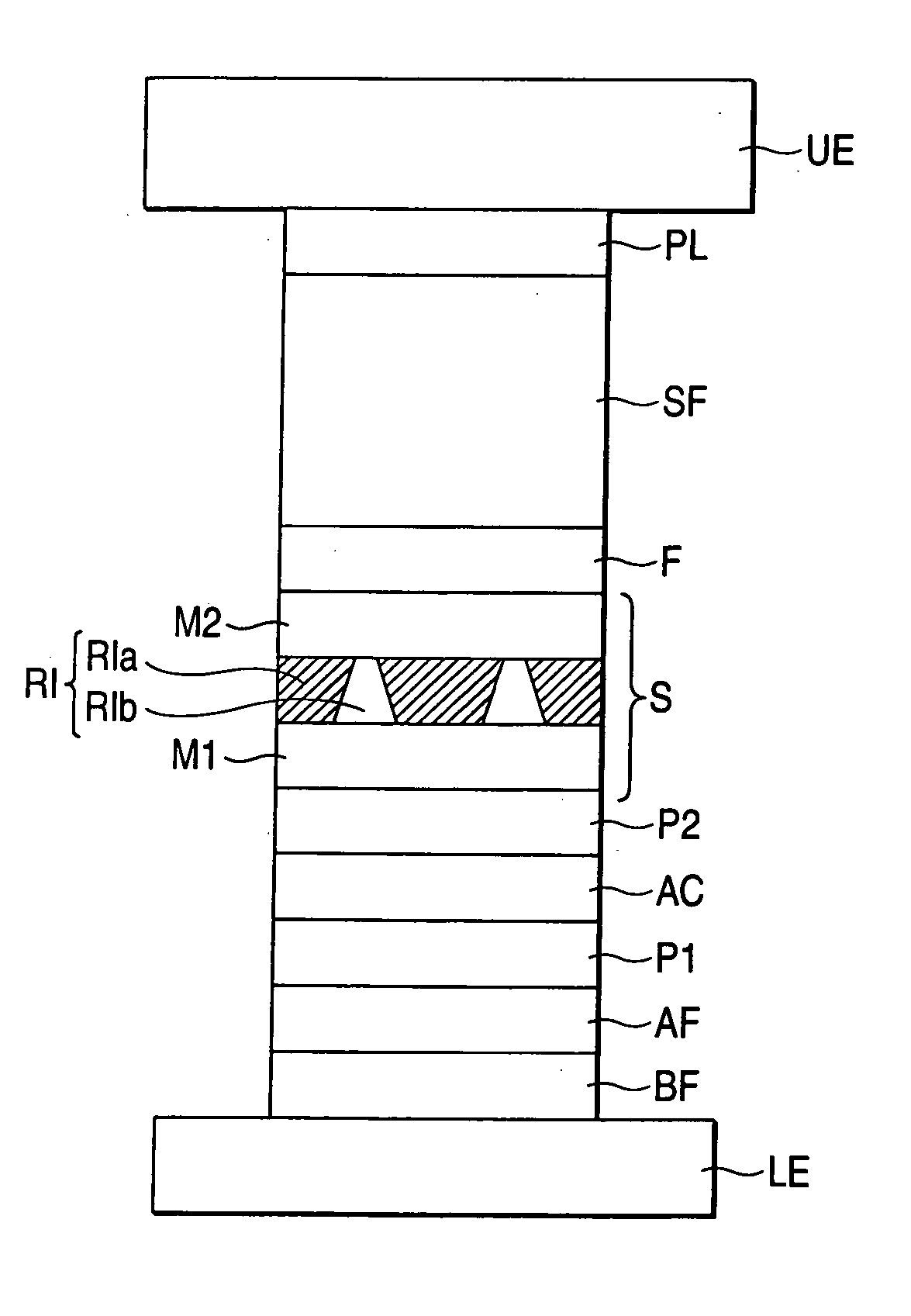
[0050]FIG. 1 is a typical view showing a sectional structure of a main portion of a magnetoresistive effect element according to a first embodiment of the invention.

[0051] Namely, the magnetoresistive effect element of this embodiment has a structure in which a laminating film structure including a spin valve structure is arranged between a lower electrode LE and an upper electrode UE. A sense current can be flowed through the lower electrode LE and the upper electrode UE in a direction substantially perpendicular to the film thickness direction of the spin valve, and GMR of the CPP type is realized.

[0052] The spin valve structure of this embodiment will be explained. A first pinned layer (magnetization pinned layer) P1, a second pinned layer (magnetization pinned layer) P2, a free layer (magnetization free layer) F, and a spacer layer (nonmagnetic metal layer) S, which is disposed between the layer P1 / P2 and the layer F, are provided.

[0053] Here, the magnetization of the first p...

second embodiment

[0087] Described as a second embodiment of the invention will be a GMR element of the CPP type in which a thick spin filter layer SF is inserted into a spin valve film including a resistance increasing layer in a free layer.

[0088]FIG. 7 is a typical view showing the sectional structure of a main portion of a magnetoresistive effect element of this embodiment. In FIG. 7, elements similar to those in the structures shown FIGS. 1 to 6 are designated by the same reference numerals, and their detailed explanations will be omitted.

[0089] The magnetoresistive effect element of this embodiment also has a spin valve structure including a pinned layer, a free layer and a spacer layer S disposed therebetween. Each of these layers has a function as mentioned above in the first embodiment. However, in this embodiment, the spacer layer S includes a single layer made of a nonmagnetic material. The free layer includes a first free layer F1, a second free layer F2 and a resistance increasing layer...

third embodiment

[0101] Described as a third embodiment of the invention will be a GMR element of the CPP type in which a thick spin filter layer SF is inserted into a spin valve film including a resistance increasing layer in a pinned layer.

[0102]FIG. 11 is a typical view showing the sectional structure of a main portion of the magnetoresistive effect element of this embodiment. In FIG. 11, elements similar to those described with reference to FIGS. 1 to 10 are designated by the same reference numerals and their detailed explanations will be omitted.

[0103] The magnetoresistive effect element of this embodiment also has a spin valve structure including a pinned layer P, a free layer F and a spacer layer S disposed therebetween. Each of these layers has a function as mentioned in the first embodiment. However, in this embodiment, the second pinned layer P2 includes a first layer P21, a second layer P22 and a resistance increasing layer RI disposed therebetween. The first and second layers P21, P22 ...


PUM

PropertyMeasurementUnit
Thicknessaaaaaaaaaa
Thicknessaaaaaaaaaa
Nanoscale particle sizeaaaaaaaaaa

Abstract

A magnetoresistive effect element includes a magnetization pinned layer, a magnetization free layer; a nonmagnetic metal layer disposed between the magnetization pinned layer and the magnetization free layer, a resistance increasing layer, a spin filter layer, and a pair of electrodes. The resistance increasing layer includes a insulation portion and is disposed in at least one of the magnetization pinned layer, the magnetization free layer, and the nonmagnetic metal layer. The spin filter layer is disposed to be adjacent to the magnetization free layer and has a thickness in a range of 5 nm to 20 nm. The magnetization free layer is disposed between the spin filter layer and the nonmagnetic metal layer. The magnetization pinned layer, the magnetization free layer, the nonmagnetic layer, the resistance increasing layer, and the spin filter layer are disposed between the electrodes.

Description

[0001] This application is based upon and claims the benefit of priority from the prior Japanese Patent Application No.2003-344030 filed on Oct. 2, 2003; the entire contents of which are incorporated herein by reference. BACKGROUND OF THE INVENTION [0002] 1. Field of the Invention [0003] The present invention relates to a magnetoresistive effect element, a magnetic head and a magnetic reproducing apparatus, and more particularly, relates to a magneto resistive effect element having a structure for flowing a sense current in a direction perpendicular to a film surface of a magnetoresistive effect film, and a magnetic head and a magnetic reproducing apparatus using this magnetoresistive effect element. [0004] 2. Description of the Related Art [0005] In recent years, compactness and an increase in capacity of a magnetic recording medium have been advanced, and the relative speed between the magnetic head for reproduction and the magnetic recording medium at an information reading time ...

Claims


Application Information

Patent Timeline
IPC IPC(8): G11B5/127G11B5/33C22C19/05G11B5/39H01L21/8246H01L27/105H01L43/08H01L43/10
CPCB82Y25/00G11B5/3906H01F10/3272H01F41/32H01F41/325H01L27/228H01L43/08H01F10/3259H01L27/224H10B61/10H10B61/22H10N50/10
Inventor YUASA, HIROMIFUKUZAWA, HIDEAKIHASHIMOTO, SUSUMUIWASAKI, HITOSHI
Owner KK TOSHIBA
Why Eureka
Try Eureka