
Slab laser and method with improved and directionally homogenized beam quality

a laser and slab technology, applied in the field of solid-state slab lasers, can solve the problems of limited scalability, lasers with cylindrical rods, and lasers that produce poor beam quality along the wide axis of the slab

Active Publication Date: 2005-05-26
RAYTHEON CO
View PDF4 Cites 31 Cited by
  • Summary
  • Abstract
  • Description
  • Claims
  • Application Information

AI Technical Summary

Benefits of technology

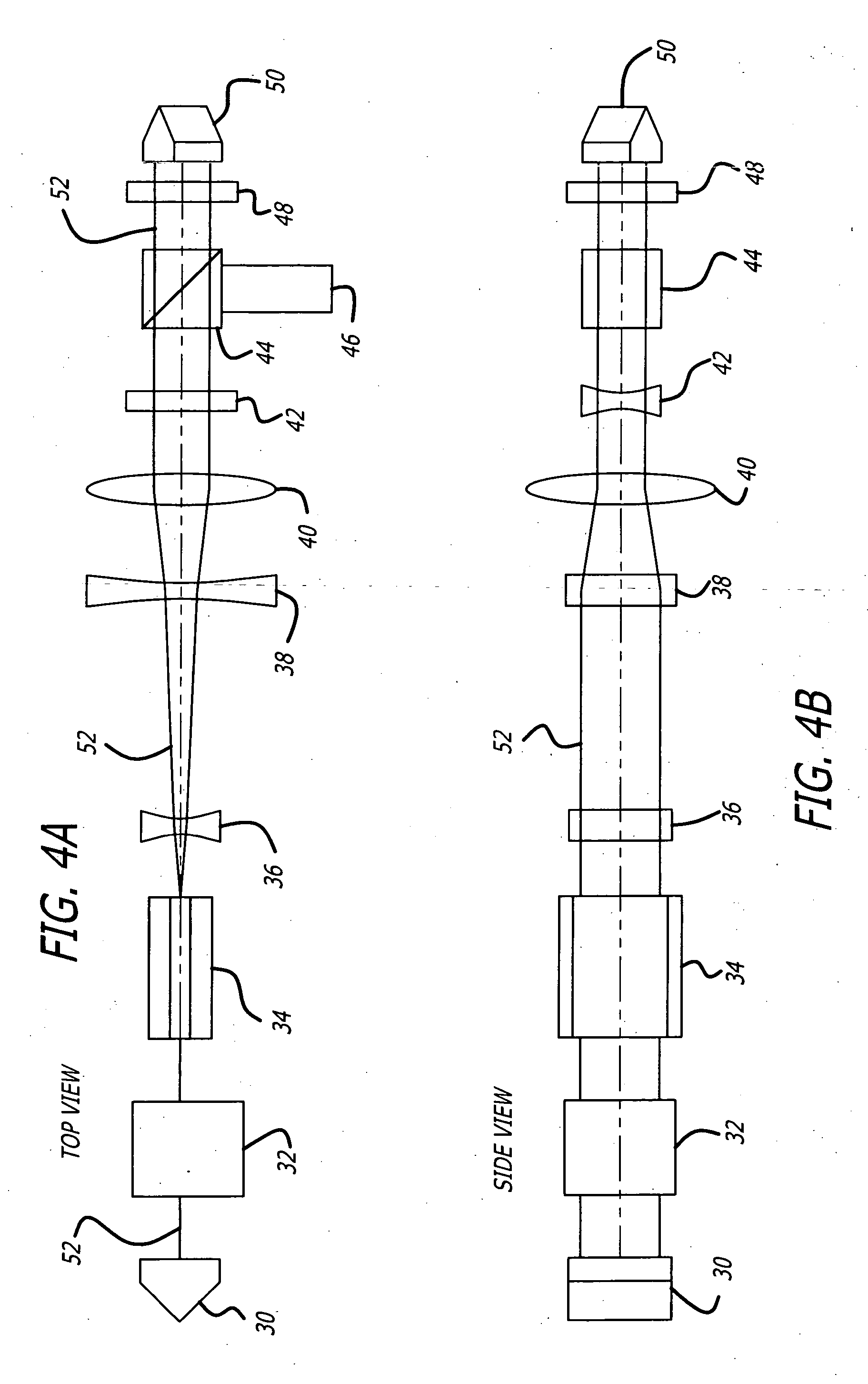
[0016] The present invention also teaches a method of generating a laser beam having beam quality along two transverse axes that is determined by the mode discrimination characteristics of one axis. This method is accomplished in a laser resonator having a slab lasing medium, an aperture stop, a first reflector aligned with a first end of the slab, an anamorphic telescope aligned with a second end of the slab, and a second reflector aligned with the telescope opposite of the slab. The steps of the method include stimulating emission of a laser beam from the ends of the slab, and limiting the profile of the laser beam by a narrow transverse dimension and an orthogonal wide transverse dimension of the aperture stop. Then reflecting, by the first reflector, the laser beam emitted from the first end of the slab back therein, thereby defining a first end of a resonant cavity. Next, reshaping the laser beam profile, by the telescope, to be substantially symmetrical about its transverse axes. Finally, rotating the beam profile of the reshaped laser beam by approximately 90°, by the second reflector, and reflecting the reshaped laser beam back into the telescope, by the second reflector, thereby defining a second end of the resonant cavity.

Problems solved by technology

Cylindrical rod lasers are particularly useful, but have limited scalability for a variety of reasons, including thermal management limitations.
However, the wider axis typically produces multi-mode beam quality unless a more complex resonator design is used in this axis.
The laser therefore produces poor beam quality along the wide axis of the slab.
First, the long length of the resonator results in a large physical volume for the laser resonator.
Second, the buildup time in a long resonator is slower, leading to long duration Q-switched pulses.
Furthermore, because the transverse mode selection for the two orthogonal directions is decoupled, the resonator may produce a beam with a different beam quality in each direction, which is undesirable in certain applications.
The unstable resonator approach cannot be used with cavity dumping, and thereby limits its utility for certain pulsed applications of interest, such as short-duration pulsed systems.

Method used


Image

  • Slab laser and method with improved and directionally homogenized beam quality
  • Slab laser and method with improved and directionally homogenized beam quality
  • Slab laser and method with improved and directionally homogenized beam quality

Examples


Embodiment Construction

[0024] Illustrative embodiments and exemplary applications will now be described with reference to the accompanying drawings to disclose the advantageous teachings of the present invention.

[0025] While the present invention is described herein with reference to illustrative embodiments for particular applications, it should be understood that the invention is not limited thereto. Those having ordinary skill in the art and access to the teachings provided herein will recognize additional modifications, applications, and embodiments within the scope thereof and additional fields in which the present invention would be of significant utility.

[0026] The teachings of the present invention are applicable to a broad range of applications requiring high power solid-state laser resonators with good beam quality in both transverse axes. It is particularly useful in applications requiring short pulse duration operation with high beam quality. Conventional high aspect ratio slab laser resonat...


PUM


Abstract

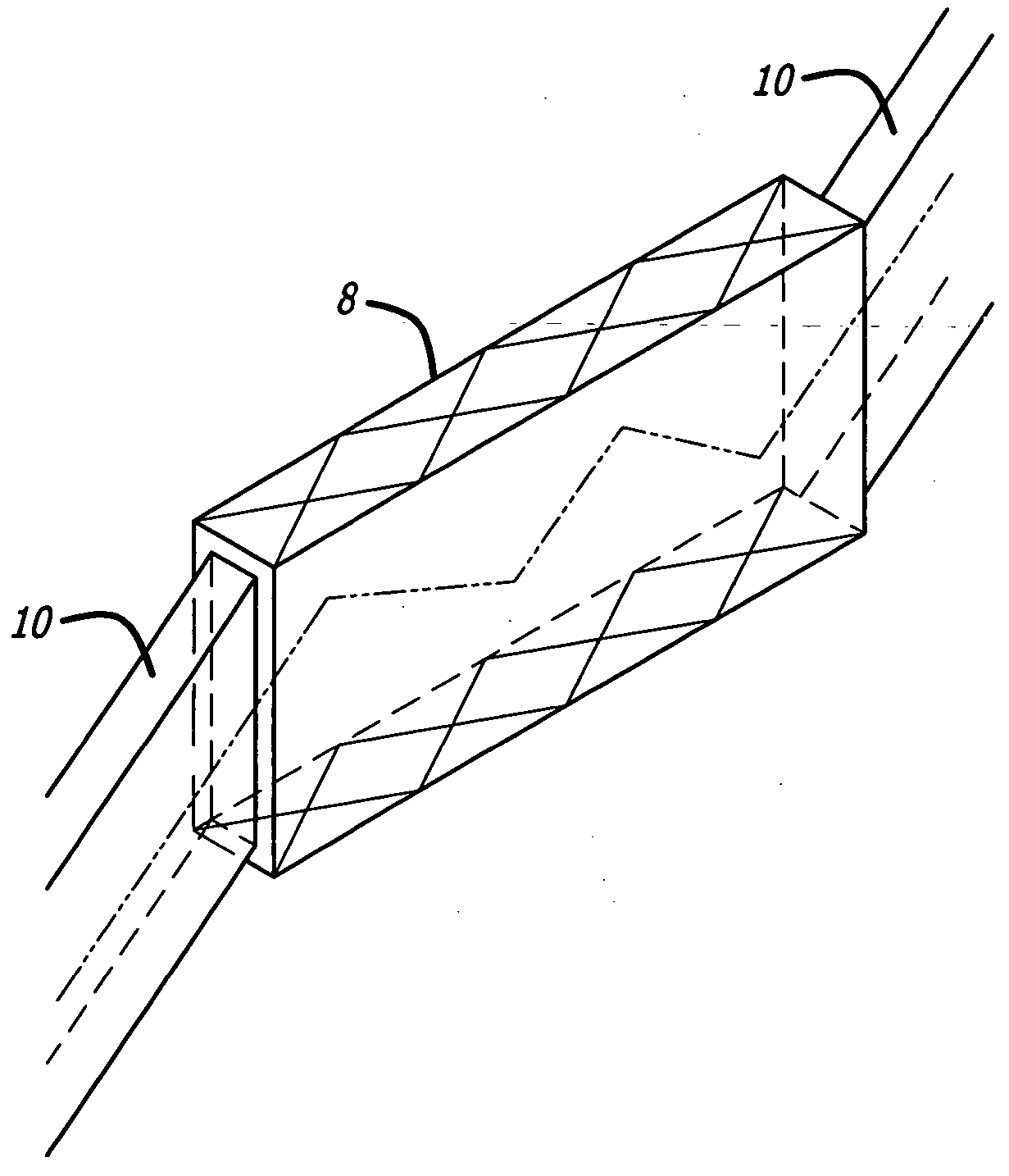
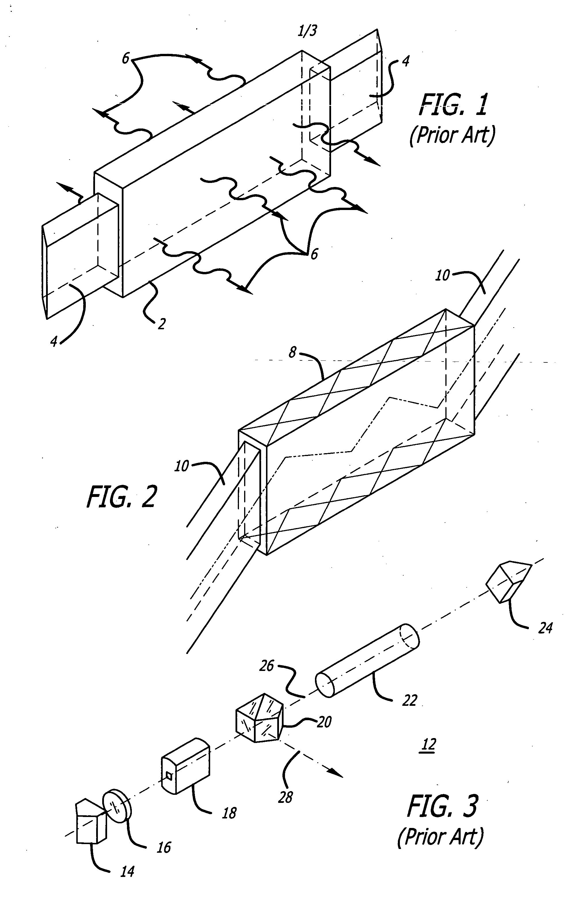
A laser resonator for generating a laser beam having beam quality along two transverse axes that is determined primarily by the mode discrimination characteristics of one axis. The apparatus including a means for providing a collimated beam of electromagnetic energy with a predetermined orientation with respect to a line of sight thereof, and, a means for rotating the beam such that a transverse mode selection therefor is the same for two orthogonal directions thereof. The first means includes a slab laser having principal axes, and the second means includes a porro prism or a Benson prism. The prism is rotated 45 degrees about the line of sight with respect to the slab axes. The beam is rotated through successive round trip passes through the slab. A telescope, or an anamorphic telescope may be disposed between the slab and the prism. The resonator has a high aspect ratio slab lasing medium with a first and a second end that emit a laser beam. An aperture stop with a narrow transverse dimension and an orthogonal wide transverse dimension defines the laser beam profile. The slab itself may define the aperture stop. A first reflector, is aligned to reflect the laser beam emitted from one end of the slab back into the slab, and thereby define a first end of a resonant cavity. An anamorphic telescope is aligned to receive and reshape the laser beam profile to be substantially symmetrical about its transverse axes. The beam profile of the reshaped laser beam is rotated 90° and reflected, by a second reflector, back into the telescope, defining the second end of the resonator. The reflectors may be porro prisms, mirrors, or Benson prisms. Polarization out-couplers are used in conjunction with electro-optic Q-switches to out-couple-laser energy. The slab may be solid state Yb:YAG.

Description

BACKGROUND OF THE INVENTION [0001] 1. Field of the Invention [0002] The present invention relates to lasers. More specifically, the present invention relates to solid-state slab lasers having high beam quality along orthogonal transverse axes. [0003] 2. Description of the Related Art [0004] Solid-state lasers are useful in a number of military and commercial applications. Many applications require high output power levels and high beam quality in order to achieve adequate beam intensity on a target in the far field. Some of these applications also require short duration pulses, which may fall into the nanosecond range. Military applications include rangefinders, designators, active tracking illuminators, beacons for atmospheric wavefront sensing, laser radar, infrared countermeasures, and directed energy weapons. Commercial applications include industrial materials processing, long-range remote sensing, and other scientific applications. Solid state lasers employ a doped insulator l...

Claims


Application Information

Patent Timeline
Patent Type & Authority Applications(United States)
IPC IPC(8): H01S3/00H01S3/06H01S3/08H01S3/0941H01S3/107H01S3/115H01S3/16
CPCH01S3/005H01S3/0606H01S3/08059H01S3/08072H01S3/08095H01S3/1643H01S3/0941H01S3/107H01S3/115H01S3/1618H01S3/0813
Inventor REEDER, ROBIN A.FILGAS, DAVID M.BYREN, ROBERT W.
Owner RAYTHEON CO
Learn More