
Optical frequency shift keying modulator

a technology of optical frequency shift and modulator, applied in the field of optical frequency shift keying modulator, can solve the problems of system inability to accommodate high-speed operation, optical ssb modulator is not exactly suitable for optical fsk modulator, etc., to achieve simple and highly precise system, increase transmission rate, and prevent the generation of parasitic intensity variations

Active Publication Date: 2005-05-26
NAT INST OF INFORMATION & COMM TECH
View PDF8 Cites 21 Cited by
  • Summary
  • Abstract
  • Description
  • Claims
  • Application Information

AI Technical Summary

Benefits of technology

[0011] An object of the present invention is to provide an optical FSK modulator which can be used for an optical information communication and the like, and which can transmit information at a high speed.
[0048] According to the present invention, an optical FSK modulator which can provide a new millimeter-wave source and microwave source can be provided.

Problems solved by technology

However, in an optical FSK system of such a method, a laser intensity changes as the laser wavelength is changed, so that there is a problem that this must be compensated.
Moreover, there is a problem that such a system cannot accommodate to a high-speed operation.
Therefore, there is a problem that the optical SSB modulator is not exactly suitable for an optical FSK modulator.

Method used


Image

  • Optical frequency shift keying modulator
  • Optical frequency shift keying modulator
  • Optical frequency shift keying modulator

Examples


Embodiment Construction

[0066] 1. Optical FSK Modulator

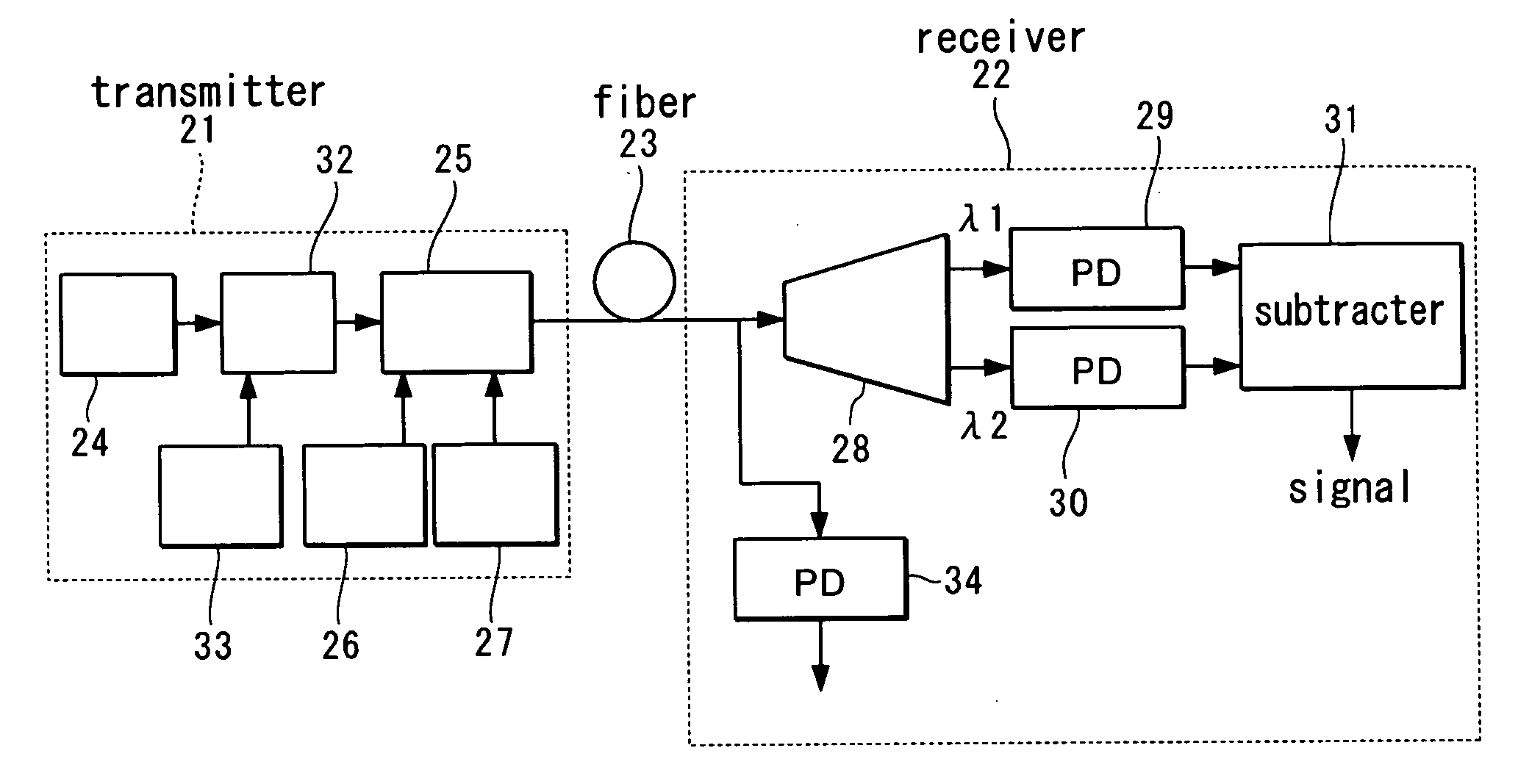
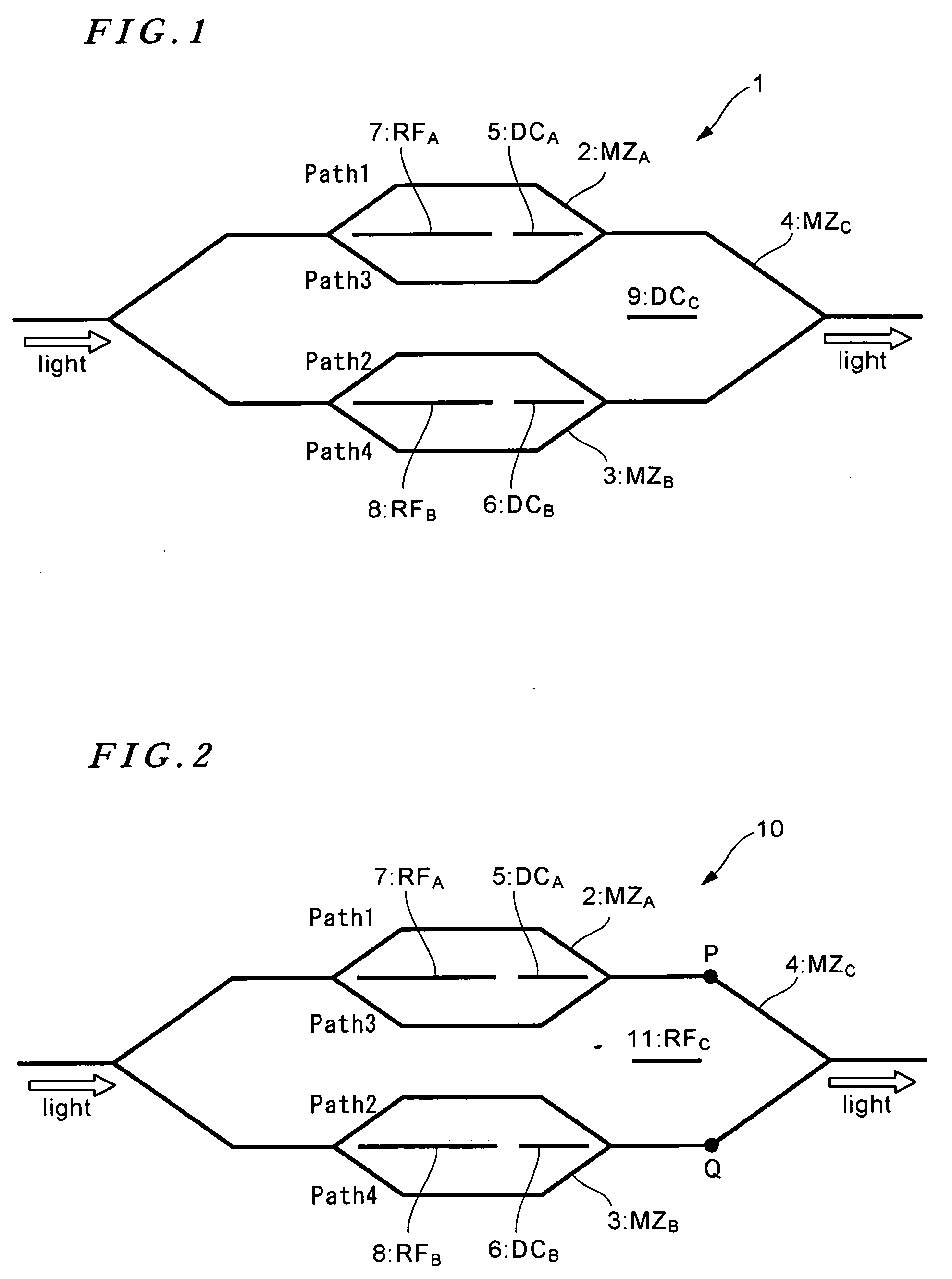
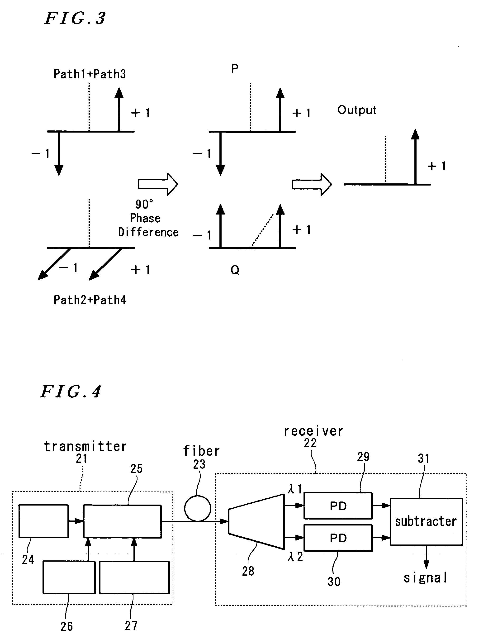
[0067] Hereinafter, an optical FSK modulator 10 according to a first embodiment of the present invention will be described referring to the drawings. FIG. 2 is a block diagram showing a basic arrangement of such an optical FSK modulator. As shown in FIG. 2, the optical FSK modulator of the present invention is provided with: for example, a first sub Mach-Zehnder waveguide (MZA) 2; a second sub Mach-Zehnder waveguide (MZB) 3; a main Mach-Zehnder waveguide (MZC) 4 including the MZA and MZB and provided with a light input portion and a modulated light output portion; a first direct-current or low-frequency electrode (DCA electrode) 5 controlling a bias voltage between two arms composing the MZA, thereby controlling a phase of light propagating in the two arms of the MZA; a second direct-current or low-frequency electrode (DCB electrode) 6 controlling a bias voltage between two arms composing the MZB, thereby controlling a phase of light propagating in th...


PUM


Abstract

An optical FSK modulator which can be used for an optical information communication is provided. The optical FSK is provided with: a second sub Mach-Zehnder waveguide (MZB) 3; a main Mach-Zehnder waveguide (MZC) 4 including the MZA and MZB and provided with a light input portion and a modulated light output portion; a first direct-current or low-frequency electrode (DCA electrode) 5 controlling a bias voltage between two arms composing the MZA, thereby controlling a phase of light propagating in the two arms of the MZA; a second direct-current or low-frequency electrode (DCB electrode) 6 controlling a bias voltage between two arms composing the MZB, thereby controlling a phase of light propagating in the two arms of the MZB; a first RF electrode (RFA electrode) 7 inputting a radio frequency (RF) signal to the two arms composing the MZA; a second RF electrode (RFB electrode) 8 inputting an RF signal to the two arms composing the MZB; and a traveling-wave-type electrode (RFC electrode) 11 controlling a voltage of the RF signal inputted, thereby controlling a frequency of light outputted from the output portion.

Description

BACKGROUND OF THE INVENTION [0001] 1. Field of the Invention [0002] The present invention relates to an optical frequency shift keying modulator and the like. [0003] 2. Description of the Related Art [0004] An optical frequency shift keying (optical FSK) is a technology which applies modulation to a frequency of light and transmits variations in the frequency as a signal. An FSK signal generally carries no information on its amplitude, so that it has a feature of being subject to a level fluctuation or noise. [0005] An FSK system using a digital signal has been already known (see e.g. Japanese patent application laid-open No. 11-17746). However, this technology is related to shifting the frequency of the digital signal, so that the frequency of light is not shifted. [0006] As a system for shifting a frequency of light, there is an optical FSK system. In a conventional optical FSK system, a laser emission wavelength itself is changed by varying an electric current provided to a tunab...

Claims


Application Information

Patent Timeline
IPC IPC(8): H04B1/69H04B10/155
CPCH04B1/7163H04B10/5563H04B10/5051H04B10/505
Inventor KAWANISHI, TETSUYAIZUTSU, MASAYUKI
Owner NAT INST OF INFORMATION & COMM TECH
Learn More