Multi-chamber system

a multi-chamber system and chamber technology, applied in the direction of conveyor parts, electrical equipment, storage devices, etc., can solve the problems of large equipment and installation costs, large large area of the facility, so as to minimize equipment and operating costs, minimize compartmental areas, and facilitate expansion

Inactive Publication Date: 2005-05-26
SAMSUNG ELECTRONICS CO LTD
View PDF23 Cites 15 Cited by
  • Summary
  • Abstract
  • Description
  • Claims
  • Application Information

AI Technical Summary

Benefits of technology

[0013] Another object of the invention is to provide a multi-chamber system which minimizes the compartmental areas in which a vacuum must be maintained, thereby minimizing equipment and operating costs.
[0014] Still another object of the invention is to provide a multi-chamber system that can be readily expanded.
[0015] Furthermore, another object of the invention is to provide a multi-chamber system that minimizes the time required to move a substrate through the system while being processed.

Problems solved by technology

Accordingly, the entire area of the facility is rather large and, in particular, the vacuum facility for maintaining a vacuum in the chambers must be correspondingly large and complex.
Of course, the large scale of the facility is responsible for high equipment and installation costs.
However, multi-chamber systems have very high purchase prices and installation costs.
In the case in which an additional multi-chamber system is added to the facility, the footprint of the multi-chamber systems would occupy a significantly large part of the clean room of the facility.
These operations of the transfer apparatus, required for processing a substrate in the system, require long amounts of time.
Thus, the conventional transfer apparatus impedes the production rate and, as such, contributes to the high cost of the completed products.

Method used


Image

  • Multi-chamber system
  • Multi-chamber system
  • Multi-chamber system

Examples


first embodiment

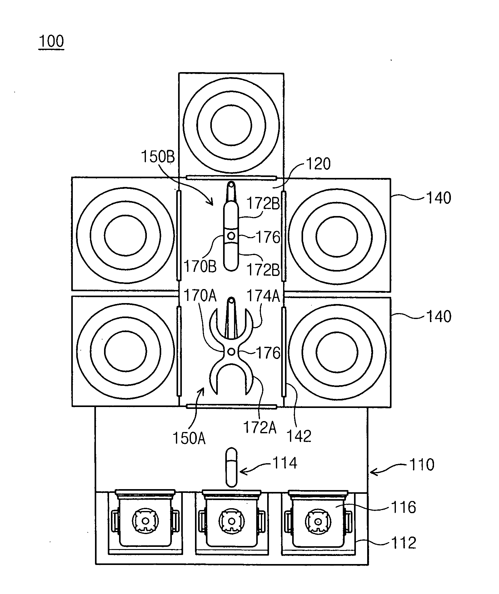
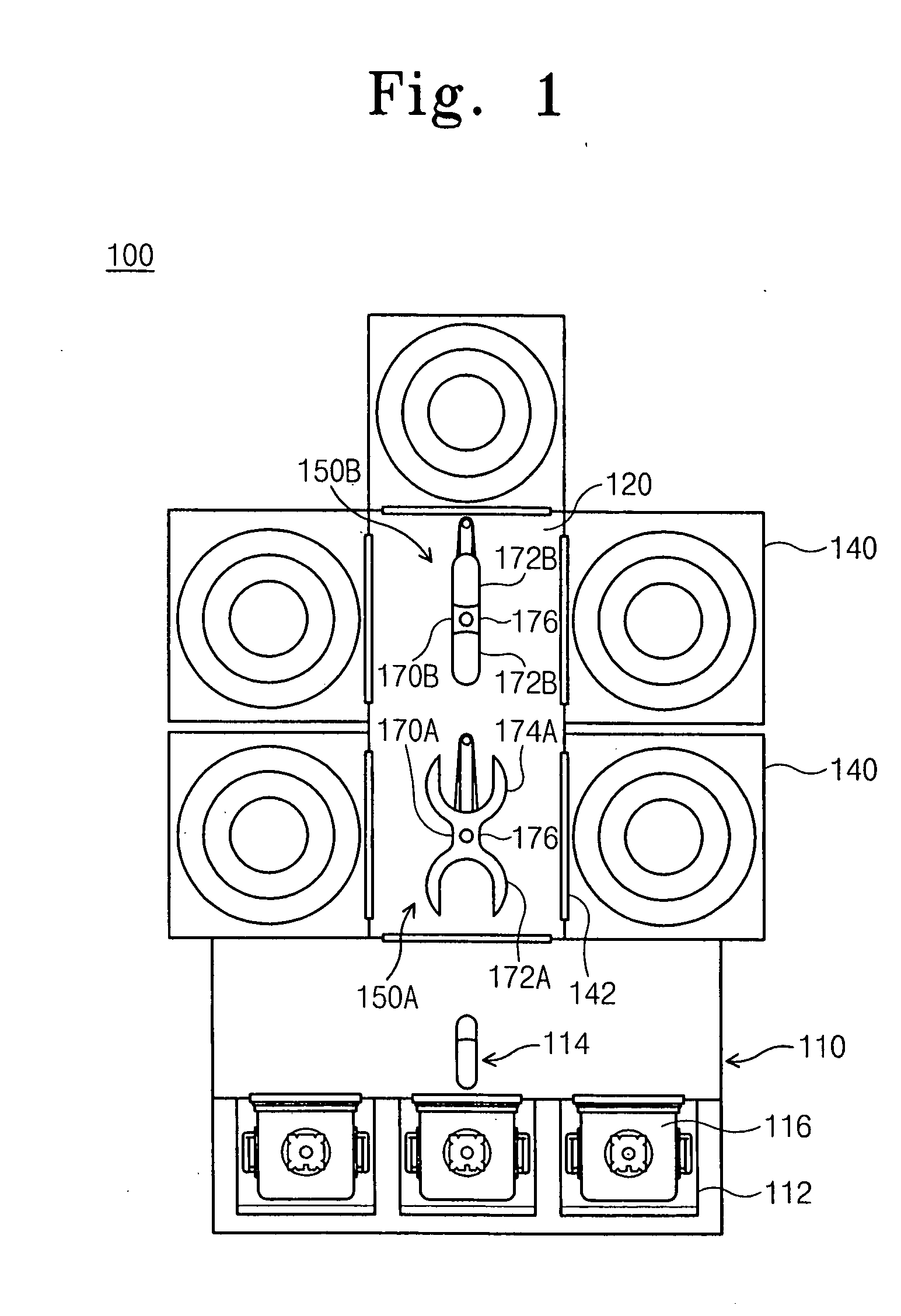
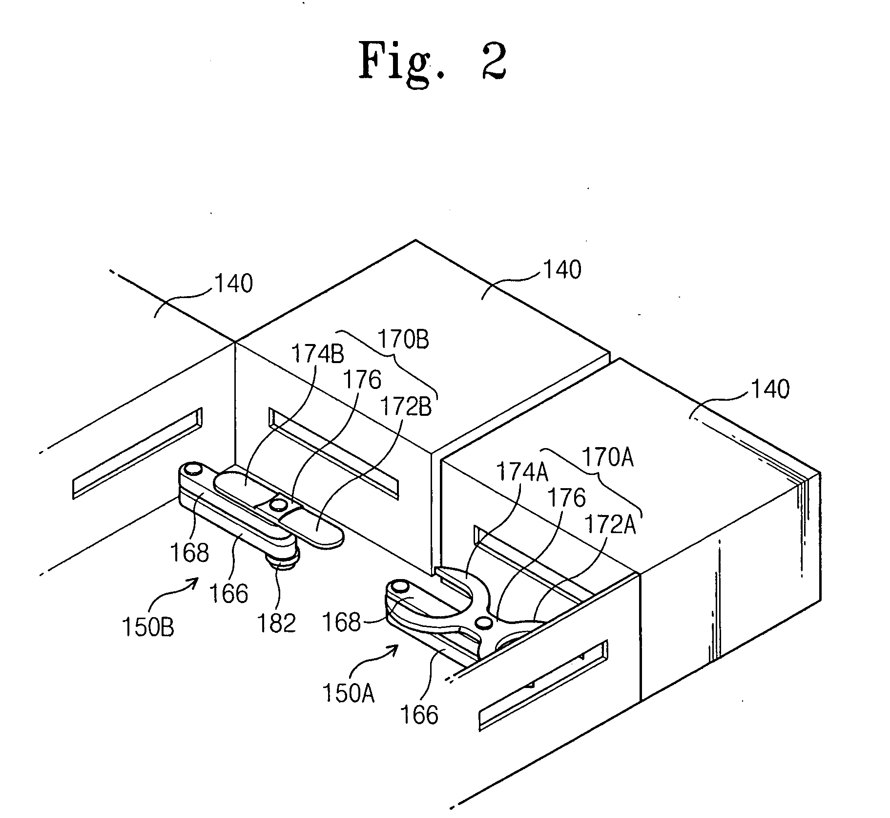
[0037] Referring to FIG. 1 and FIG. 2, a multi-chamber system 100 according the present invention includes an index station 110, a transfer passageway 120, five process chambers 140 connected to the transfer passageway 120, and dual substrate transfer apparatus comprising a first robot 150A and a second robot 150B disposed in the transfer passageway 120.

[0038] The index station 110 may comprise an equipment front end module (EFEM) having FOUP openers 112 and a single substrate transfer robot 114. Three front opening unified pods (FOUPs) 116 are mounted on the FOUP openers 112 of the index station 110, respectively. FOUPs are typically used as substrate carriers in mass production and can be installed at the index station 110 by means of an automatic transport system, e.g., an overhead hoist transport (OHT) vehicle, automatic guided vehicle (AGV), or rail guided vehicle (RGV). The index station 110 is connected to one end of the transfer passageway 120.

[0039] The first robot 150A is...

second embodiment

[0060] a multi-chamber system 200 according to the present invention is illustrated in FIG. 19. The multi-chamber system 200 includes an index station 210, a transfer passageway 220, process chambers 240, and dual substrate transfer apparatuses 250 each of which has the same structure and function as that of the first embodiment of FIG. 1. However, in the second embodiment, a single substrate transfer apparatus 214 for loading / unloading a substrate into / from a FOUP is installed in the transfer passageway 220. Alternatively, a dual transfer apparatus can be used in place of the single substrate transfer apparatus 214. One end of the transfer passageway 220 abuts the index station 210. A plurality of FOUPs are disposed on respective FOUP openers 212 of the index station 210.

[0061] Furthermore, the multi-chamber system 200 includes vacuum loadlock chambers 230 connected to both sides of the transfer passageway 220, and vacuum process chambers 240 connected to each of the loadlock chamb...


PUM


Abstract

A multi-chamber system includes an index station at which one or more substrate cassettes are placed, a transfer passageway having one end adjacent the index station, at least one process chamber disposed alongside the transfer passageway, and at least one substrate transfer robot disposed in the transfer passageway for receiving a substrate from the index station and by which the substrate is transferred to each process chamber. The multi-chamber system has a minimal footprint. Furthermore, the system can be easily expanded. In addition, the substrate transfer robot(s) may have a blade including two substrate supports so that the time required for moving a substrate through the system is minimized.

Description

BACKGROUND OF THE INVENTION [0001] 1. Field of the Invention [0002] The present invention is directed to a multi-chamber system for manufacturing semiconductor devices. [0003] 2. Description of the Related Art [0004] In general, a cluster system is a multi-chamber type of apparatus that includes a transfer robot (or handler) and a plurality of processing modules disposed around the transfer robot. Today, there is an increasing demand for cluster systems that can execute a plurality of processes in the manufacturing of semiconductor devices and the like. [0005] For instance, a cluster system is used to dry etch semiconductor wafers with plasma. This cluster system comprises a plurality of process chambers in which a high vacuum environment, necessary for creating the plasma, is maintained. The cluster system also includes a centralized transfer chamber in which a transfer apparatus is disposed. The transfer apparatus is operative to load / unload wafers to / from the process chambers. [0...

Claims


Application Information

Patent Timeline
Patent Type & Authority Applications(United States)
IPC IPC(8): B65G1/00H01L21/3065
CPCH01L21/67745H01L21/67742H01L21/3065
Inventor KIM, KI-SANGCHAE, SEUNG-KILEE, IN-HO
Owner SAMSUNG ELECTRONICS CO LTD
Why Eureka
Try Eureka