Centrifugal impeller

a centrifugal impeller and impeller technology, applied in the field of centrifugal impellers, can solve the problems of difficult uniform injection of resin to the peripheral edge portion of the impeller at injection molding process using a mold, and achieve the effects of reducing aerodynamic load, avoiding defects or drawbacks, and avoiding aerodynamic load

Active Publication Date: 2005-05-26
ENPLAS CORP
View PDF6 Cites 30 Cited by
  • Summary
  • Abstract
  • Description
  • Claims
  • Application Information

AI Technical Summary

Benefits of technology

[0008] An object of the present invention is to substantially eliminate defects or drawbacks encountered in the prior art mentioned above and hence to provide a centrifugal impeller having a compact and strong structure, capable of reducing an aerodynamic load and maintaining a well-balanced flow of the resin at a resin injection molding process.
[0019] According to the centrifugal impeller of the present invention of the characters mentioned above, since the thickness reduced portion is formed adjacent to the rib member, the total weight of the impeller can be reduced and, hence, the centrifugal force to be applied to the impeller when rotated can be reduced. In addition, even at a time when the impeller is rotated at a high speed, the destroy of the impeller can be suppressed.
[0020] Furthermore, the arrangement of the ring-shaped rib member can prevent the lowering in mechanical strength of the impeller because of the formation of the thickness reduced portion and ensure the strength or stiffness thereof against the centrifugal force even at the high speed rotation of the impeller.
[0021] Furthermore, since the rib member has a ring shape coaxial with the central axis of the boss portion, the rib member does not constitute a resistance when the impeller rotates around the rotational shaft inserted into the boss portion, thus reducing an aerodynamic load at the rotating time.
[0022] Still furthermore, since the impeller has a symmetrical peripheral shape around the boss portion, the flow of resin at an injection molding process can be well-balanced, and a mold can be easily formed.

Problems solved by technology

In addition, since the ribs and the thickness reduced portion are alternately formed to portions around the boss portion, it is difficult to feed the resin uniformly to the peripheral edge portion of the impeller at an injection molding process using a mold.

Method used


Image

  • Centrifugal impeller
  • Centrifugal impeller
  • Centrifugal impeller

Examples


Embodiment Construction

[0029] One preferred embodiment of the present invention will be described hereunder with reference to the accompanying drawings.

[0030] First, with reference to FIG. 4, showing a turbo-charger 11, the turbo-charger 11 has a bearing portion 12 at its central portion, a turbine section 13 on a right-side, as viewed, of the bearing portion 12 and a compressor section 14 on a left-side thereof.

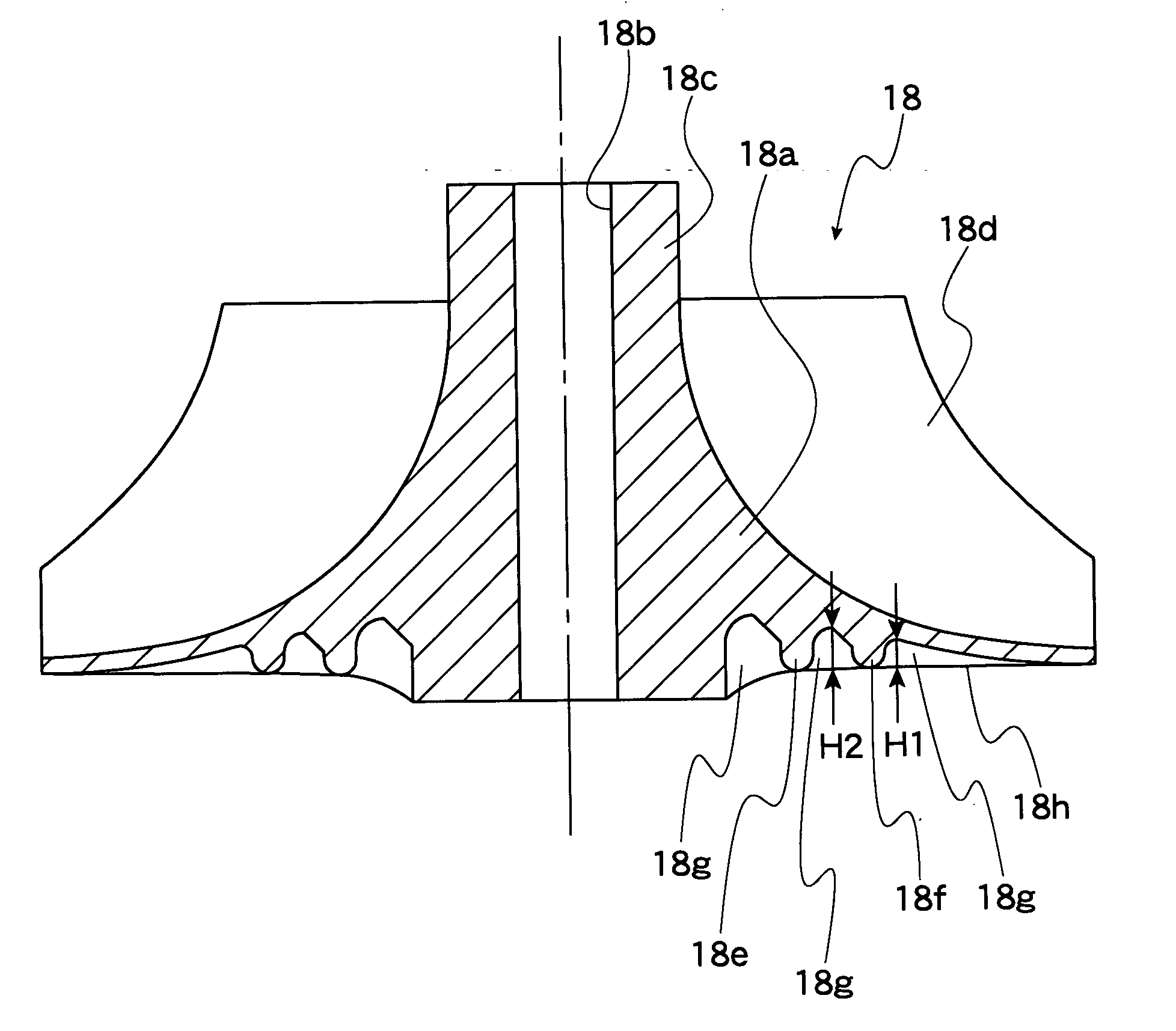
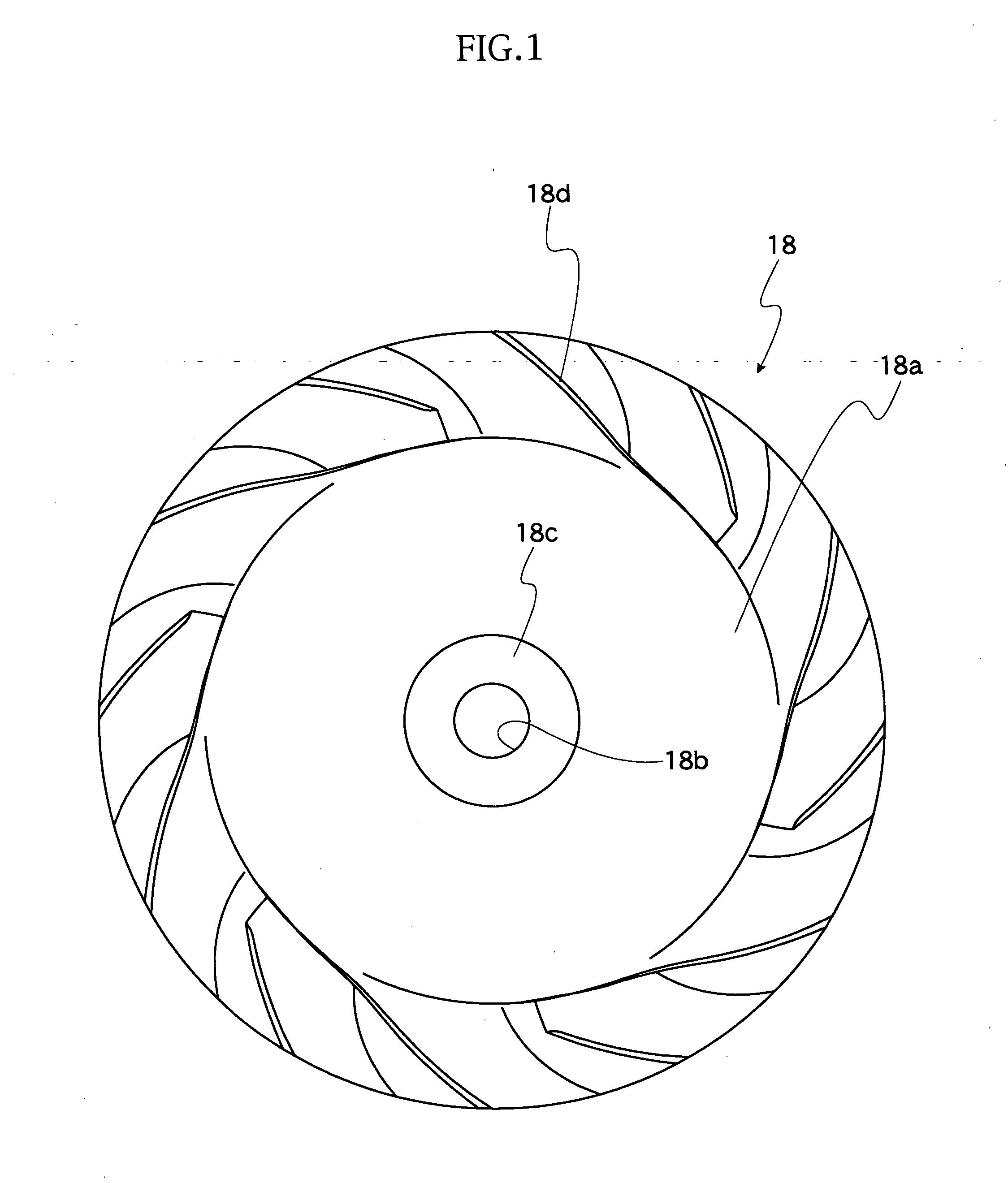
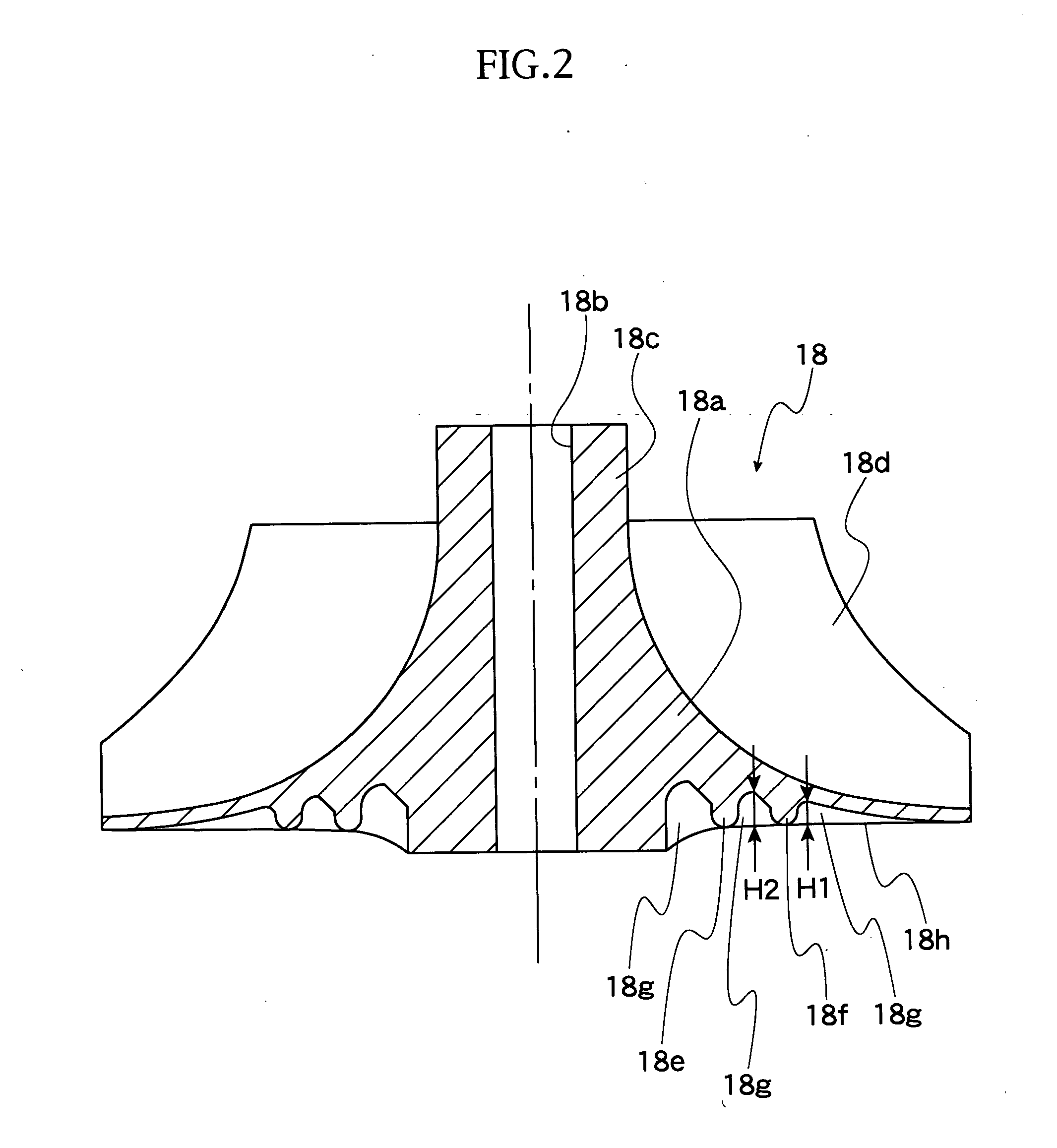
[0031] A rotor 19 including a rotating shaft 16, a turbine wheel 17 and an impeller 18, as blade wheel, is supported to be rotatable by the bearing portion 12.

[0032] The rotating shaft 16 is provided, at its left end portion, with a small-sized (small diameter) impeller mount 26, to which the impeller 18 is fitted and fixed thereto by a nut 27. The rotating shaft 16 also has a right end portion to which a nut 28 is fixed. A nut 28 is firmly screwed by a bolt 29 to thereby fasten the turbine wheel 17.

[0033] In the turbine section 13, an engine exhaust gas fed from an inlet port 21 of a casing 2...


PUM

PropertyMeasurementUnit
ring-shape aaaaaaaaaa
thicknessaaaaaaaaaa
pressureaaaaaaaaaa

Abstract

A centrifugal impeller particularly for a turbo-charger includes a circular disc member, a boss portion formed at a central portion of the disc member and having a central through hole into which a rotational shaft is inserted, an impeller blade integrally formed on one surface side of the disc member, and a ring-shaped rib member arranged on the other surface side of the disc member so as to be coaxial with a center axis of the boss portion. A thickness reduced portion is formed to the disc member so as to have a thickness smaller than that of another portion of the disc member, and the thickness reduced portion is arranged adjacent to the rib member.

Description

BACKGROUND OF THE INVENTION [0001] 1. Field of the Invention [0002] The present invention relates to an impeller, and more particularly, a centrifugal impeller utilized for a compressor of, for example, a turbo-charger. [0003] 2. Related Art [0004] There is known a centrifugal impeller of the type mentioned above such as disclosed in Japanese Utility Model Laid-open Publication No. HEI 2-132820, for example. A turbo-charger disclosed in this publication is provided with a turbo-wheel driven by an energy of an exhaust gas from an engine of the turbo-charger, and the turbo-wheel is coupled with an impeller through a rotating (rotational) shaft so that the driving force of the turbo-wheel is transmitted to the impeller through the rotating shaft to rotate the impeller, and according to the rotation of the impeller, intake pressure on the intake (air-suction) side of the engine is increased and then supplied to the engine. [0005] Such impeller is formed with a thickness reduced portion ...

Claims


Application Information

Patent Timeline
Patent Type & Authority Applications(United States)
IPC IPC(8): F04D25/04F02B39/00F04D29/02F04D29/28
CPCF04D25/04F04D29/284F04D29/023F05D2300/44F05D2230/54
Inventor FUKIZAWA, TAISATO, ISSEI
Owner ENPLAS CORP
Why Eureka
Try Eureka