
Lightweight structure particularly for an aircraft

a technology for aircraft and light weight, applied in the field of light weight structure, can solve the problems of monolithic sheet metals, high production cost, and poor static strength characteristics of conventional fiber composite materials, and achieve the effects of improving damage tolerance, preventing crack propagation or crack formation, and slowing down crack propagation

Active Publication Date: 2005-05-26
AIRBUS OPERATIONS GMBH
View PDF19 Cites 28 Cited by
  • Summary
  • Abstract
  • Description
  • Claims
  • Application Information

AI Technical Summary

Benefits of technology

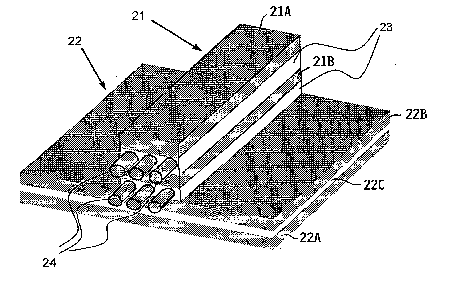
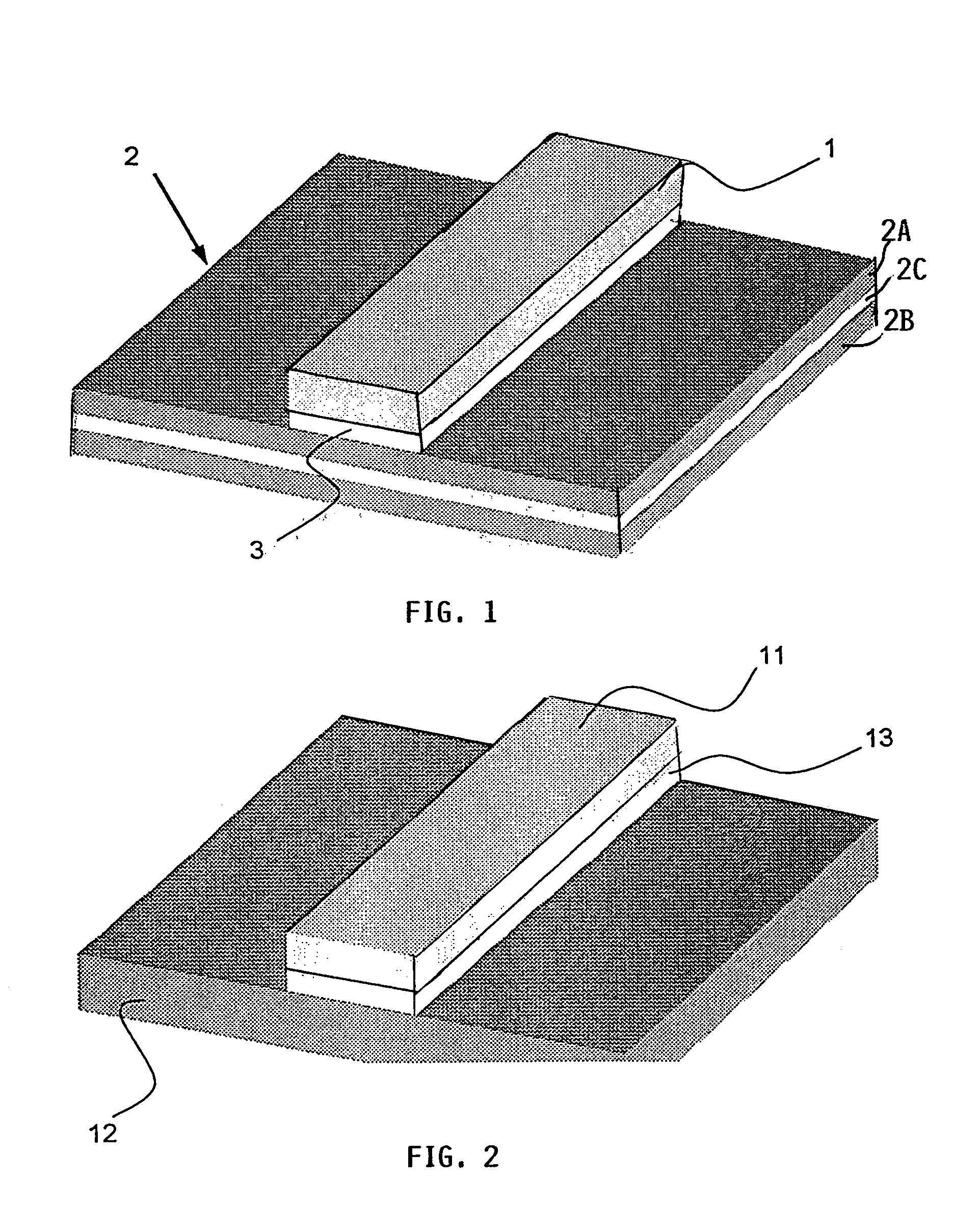
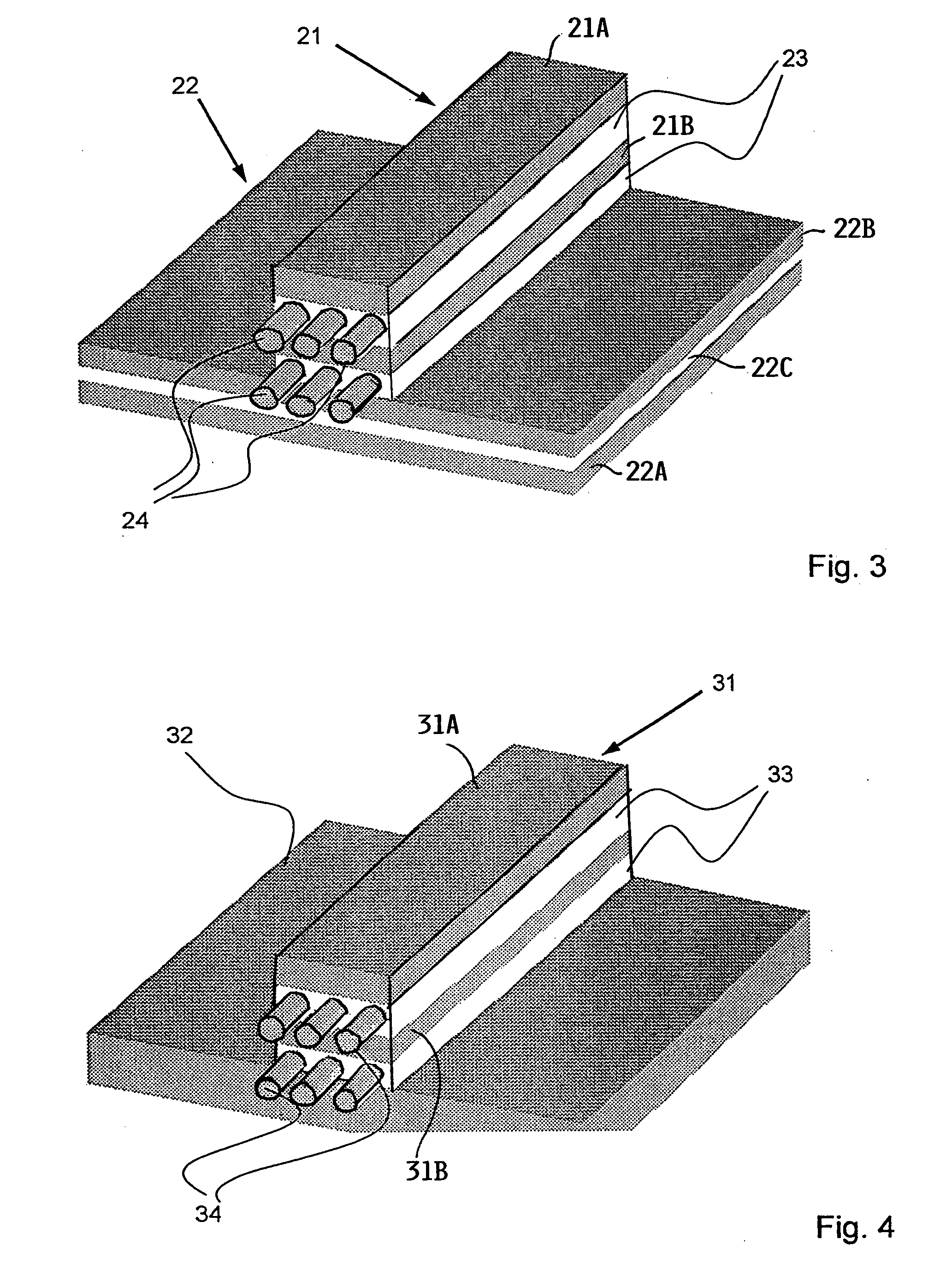
The invention is about improving the damage tolerance of lightweight structures, such as aircraft body skins, by adding reinforcing strips to the outer surface. These reinforcing strips, made of a material that can withstand damage, slow down or prevent cracks from spreading in the structure. This results in a longer lifespan for the structure and reduces the need for maintenance. The reinforcing strips can be arranged in a lattice work or crosswise to the direction of crack propagation. The use of additional reinforcing strips allows for a significant reduction in the weight of the structure, making it more efficient.

Problems solved by technology

Conventional fiber composite materials have, to some extent, static strength characteristics that are not as good as such static strength characteristics of monolithic materials.
Furthermore, the production of fiber reinforced laminated materials is subject to a substantial effort and expense compared to monolithic sheet metals, due to the needed preparation of thin sheet metal layers for the adhesive bonding with additional prepreg films and due to the necessity of manually positioning and preparing for the following adhesive bonding step.
As a result, the production costs for laminated composite materials can be significantly higher than the costs for producing monolithic sheet metals.

Method used


Image

  • Lightweight structure particularly for an aircraft
  • Lightweight structure particularly for an aircraft
  • Lightweight structure particularly for an aircraft

Examples


Embodiment Construction

[0022] Referring first to FIG. 6 for an overview of the invention when it is used in an aircraft body, longitudinally extending stringers S1, S2 form with circumferentially extending ribs an aircraft body frame or framework FW. An outer skin OS covers the framework FW outwardly. In a preferred embodiment according to the invention a lattice work LW is adhesively bonded to the inwardly facing side of the outer skin between the ribs R1, R2 and the stringers S1, S2. As shown the lattice work LW of the preferred embodiment comprises rows R and columns C of reinforcing strips adhesively bonded to the inner surface of the outer skin OS and to each other. While the lattice work of reinforcing strips is preferred, the reinforcing strips may be arranged only as columns or only as rows. In any such embodiments the angular orientation of the columns C and / or rows R relative to the stringers and relative to the ribs will be such that the reinforcing strips cross propagation directions of cracks...


PUM

PropertyMeasurementUnit
lengthaaaaaaaaaa
thicknessaaaaaaaaaa
widthaaaaaaaaaa

Abstract

An outer skin, for example of an aircraft body, is supported by a frame of longitudinal girders and circumferential ribs interconnecting the girders. Additionally, the outer skin is strengthened by reinforcing strips adhesively bonded to the outer skin between the ribs and girders. The reinforcing strips are made of material that is damage tolerant, for example high strength aluminum alloys and fiber composite materials are suitable for making the reinforcing strips. These reinforcing strips may extend in parallel to the stringers and / or the ribs and preferably form a lattice work. The reinforcing strips need not cross each other at right angles but should cross a crack propagation direction in the outer skin.

Description

PRIORITY CLAIM [0001] This application is based on and claims the priority under 35 U.S.C. §119 of German Patent Application 103 30 709.5, filed on Jul. 8, 2003, the entire disclosure of which is incorporated herein by reference. FIELD OF THE INVENTION [0002] The invention relates to a lightweight structure such as an outer skin secured to a frame structure of an aircraft body. BACKGROUND INFORMATION [0003] Lightweight structures particularly as used in the aircraft technology and in spacecraft technology, frequently comprise an outer skin, the inwardly facing surface of which is reinforced by a frame structure which herein is referred to as a “two-dimensional” stiffening, compared to the entire body which is “three-dimensional”. The aircraft body is constructed of longitudinally extending stringers and circumferentially extending ribs to which the outer skin is secured, whereby the skin is reinforced by the stringers and ribs. In designing such lightweight structures special attent...

Claims


Application Information

Patent Timeline
Patent Type & Authority Applications(United States)
IPC IPC(8): B32B3/08B32B3/14B32B15/08
CPCB32B3/08B32B15/08B32B3/14Y10T428/249924B32B2311/18B32B15/20B32B2260/021B32B2260/046B32B27/38B32B2305/08B32B15/092B32B7/12
Inventor SCHMIDT, HANS-JUERGENVICHNIAKOV, ALEXEI
Owner AIRBUS OPERATIONS GMBH
Learn More