Chemical mechanical polishing pad

Inactive Publication Date: 2005-05-26
JSR CORPORATIOON
View PDF7 Cites 25 Cited by
  • Summary
  • Abstract
  • Description
  • Claims
  • Application Information

AI Technical Summary

Benefits of technology

[0010] It is an object of the present invention which has been made to solve the above problems of the prior art to provide a chemical mechanical polishing pad whic

Problems solved by technology

It is known that the polishing result is greatly affected by the shape and properties of the chemical mechanical polishing pad in this CMP.
However, the multi-layered pad improves the above problem to a certain extent but is not a drastic solution.
It i

Method used


Image

  • Chemical mechanical polishing pad
  • Chemical mechanical polishing pad
  • Chemical mechanical polishing pad

Examples


example 1

(1) Manufacture of Chemical Mechanical Polishing Pad

(1-1) Preparation of Composition for Chemical Mechanical Polishing Pads

[0076] 80 parts by volume (equivalent to 72.2 parts by weight) of 1,2-polybutadiene (JSR RB830 (trade name) of JSR Corporation) and 20 parts by volume (equivalent to 27.2 parts by weight) of β-cyclodextrin (Dexy Pearl β-100 (trade name) of Bio Research Corporation of Yokohama, average particle diameter of 20 μm) were kneaded together at 60 rpm by an extruder heated at 160° C. for 2 minutes. Thereafter, Percumyl D (trade name, manufactured by NOF Corporation, containing 40% by mass of dicumyl peroxide) was added in an amount of 0.722 parts by weight (equivalent to 0.4 parts by weight of dicumyl peroxide based on 100 parts by weight of 1,2-polybutadiene) and further kneaded at 60 rpm and 120° C. for 2 minutes to obtain a pellet of a composition for chemical mechanical polishing pads.

(1-2) Formation of Rough Shape of Pad

[0077] This pellet was heated at 170° ...

example 2

[0120] A chemical mechanical polishing pad was manufactured in the same manner as in (1) manufacture of chemical mechanical polishing pad of Example 1 and a base layer made of foamed polyurethane having the same plane shape and the same thickness as that of the polishing pad was fixed on the non-polishing side (rear surface) by a double-coated adhesive tape having the same plane shape as the polishing pad. Further, a double-coated adhesive tape having the same plane shape as the polishing pad was affixed to the rear surface of the base layer. Then, portions covering the light transmitting area of the pad of the double-coated adhesive tape affixed to the rear surface of the pad, the base layer and the double-coated adhesive tape affixed to the rear surface of the base layer were cut away to manufacture a chemical mechanical polishing pad comprising the base layer.

[0121] The chemical mechanical polishing performance was evaluated in the same manner as in Example 1 except that the man...

example 3

[0122] A pellet of a composition for chemical mechanical polishing pads was obtained in the same manner as in (1-1) preparation of composition for chemical mechanical polishing pads of Example 1.

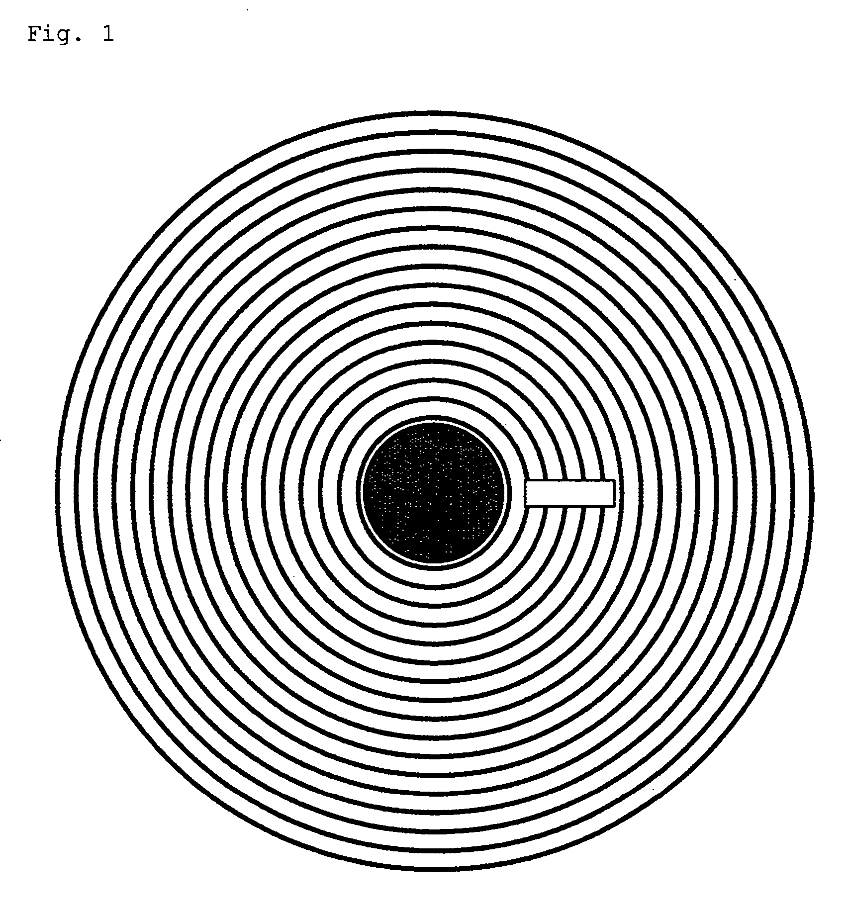
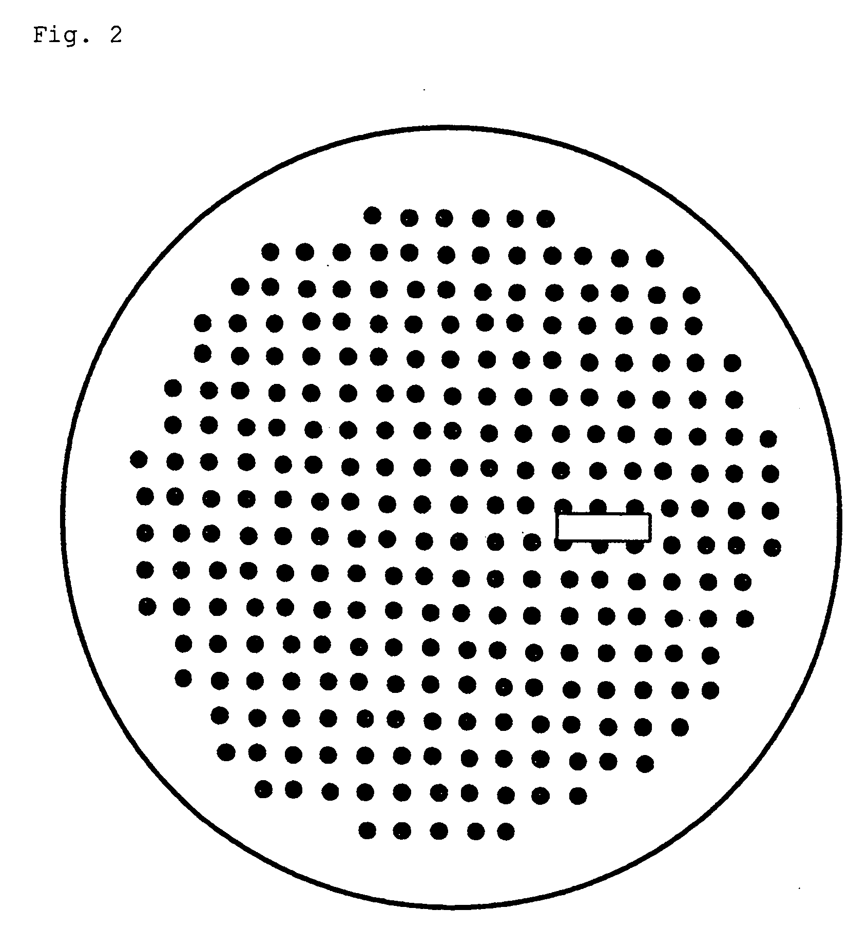
[0123] This pellet was heated in a mold having a planished projection portion and a large number of columnar projection portions in part of the bottom force at 170° C. for 18 minutes to be crosslinked so as to produce a disk-like molded product having a diameter of 600 mm and a thickness of 2.5 mm. The above planished projection portion had a long diameter of 59 mm, a short diameter of 21 mm and a height of 0.6 mm, the center thereof was located at a position 100 mm away from the center of the rough shape of a circular pad, and a straight line passing the center of the projection portion and parallel to the long diameter side was parallel to the direction of diameter of the rough shape of the circular pad. The above large number of columnar projection portions had a diameter of 5 mm and a h...


PUM


Abstract

A chemical mechanical polishing pad having a face for polishing an object to be polished, a non-polishing face opposite to the face and a side face for interconnecting these faces and including the pattern of recessed portions which are formed on the non-polishing face and are open to the non-polishing face and not to the side face.

Description

FIELD OF THE INVENTION [0001] The present invention relates to a chemical mechanical polishing pad. DESCRIPTION OF THE PRIOR ART [0002] In the manufacture of a semiconductor device, CMP (Chemical Mechanical Polishing) has been attracting much attention as a polishing technique capable of providing an extremely flat surface to a silicon substrate or a silicon substrate having wires, electrodes, etc. formed thereon (to be referred to as “semiconductor wafer” hereinafter). CMP is a technique for polishing the surface by letting an aqueous dispersion for chemical mechanical polishing (aqueous dispersion of abrasive grains) flow down the surface of a chemical mechanical polishing pad while the pad and the surface to be polished are brought into slide contact with each other. It is known that the polishing result is greatly affected by the shape and properties of the chemical mechanical polishing pad in this CMP. Therefore, various chemical mechanical polishing pads have been proposed up ...

Claims


Application Information

Patent Timeline
IPC IPC(8): B24B37/20H01L21/304B24D11/00B24D13/14C09K3/14
CPCY10S451/921B24B37/205H01L21/304B24D11/00C09K3/14
Inventor MIYAUCHI, HIROYUKISHIHO, HIROSHIKAWAHASHI, NOBUO
Owner JSR CORPORATIOON
Why Eureka
Try Eureka