Supercharge Your Innovation With Domain-Expert AI Agents!

Universal croquet wicket lighting unit

a wicket lighting and wicket technology, applied in the field of croquet, can solve the problems of affecting the play of yard croquet, affecting the play of ball sports, etc., and achieve the effects of long service life, excellent impact resistance, and high luminosity

Inactive Publication Date: 2005-05-26
LANG DAVID DELL
View PDF7 Cites 0 Cited by
  • Summary
  • Abstract
  • Description
  • Claims
  • Application Information

AI Technical Summary

Benefits of technology

"The invention is a device that combines modern materials and technology to play croquet under low illumination. It uses a single light emitting diode for illumination, which provides high luminosity, impact resistance, and efficient light emission resulting in low operating cost. The device is attached to existing wickets on the croquet course using hook-and-loop straps and is compatible with all styles of wicket. The attachment scheme is secure and stable against moving. The device has several advantages, including providing a light image of the wicket, creating a convenient aim point for long distance shots, and providing broader illumination coverage around the wicket. It also helps to avoid tripping hazards when attached to wickets distributed around a yard."

Problems solved by technology

Yard croquet is frequently played under poor lighting conditions since social events typically extend into the evening.
Diminishing daylight often curtails croquet play, since yard party lighting conditions are usually inadequate for seeing wicket positions or the passage of balls through wickets.
This problem is exacerbated by wickets' being commonly fabricated from wire, making them difficult to see and determine if a ball has in fact passed through, or merely close beside, the wicket.
Poorly illuminated wickets also present a tripping hazard for those walking on the course.
This generally fails to clearly expose position or orientation of all the wire wickets as it is difficult to sufficiently illuminate an entire course in this fashion, especially if it meanders around corners of houses and garden areas, etc.
Wide area lighting of sufficient brightness to clearly illuminate wire wickets at a distance is usually too bright to be aesthetically appealing for a night time social event.
This is unsatisfactory because the resulting diffuse illumination does not reveal a wicket so as to allow a distant player to see its exact center or orientation as needed to aim a ball through the wicket; furthermore, it does not clearly reveal the passage of a ball through a wicket.
In addition, the candle and sack are subject to being struck by a ball, upsetting the sack, and possibly creating a fire hazard.
Such a technique has many drawbacks, all related to the use of luminous paint.
All of these paints are unable to provide area illumination other than at the actual surface to which the paint is applied.
A painted item provides light that can be seen at a distance, but not light strong enough to illuminate surrounding areas.
This weakness is particularly troublesome in the case of wickets.
a. Luminous paints energized by pre-exposure suffer from low luminosity for this application.
Furthermore the amount of illumination deteriorates rapidly with time, so that only limited use is possible before the paint must be re-energized by exposure to light.
It is questionable whether the duration of useful illumination would be long enough for a typical game of croquet.
b. Luminous paints that derive their luminosity from admixture with a radioactive substance suffer from low luminosity for the application of illuminating croquet play, and also may pose toxic hazards.
Such paints are expensive and would likely be prohibitive to use in the quantities required for a consumer croquet set.
This requires conventional power on the course, as well as a set up of wide area ultraviolet lighting, all of which present inconveniences.
It is likely because of these drawbacks that products based on the claims of U.S. Pat. No. 280,807 are not being marketed.
Installation abuse can be substantial when the playing surface is hard ground; the thicker the wicket stanchion, the larger the force required to embed the wicket in the ground.
This, in combination with the suggested utilization of plastics for wicket construction could eventuate in wicket installation damage.
Alternative embodiments propose a complex dual-thickness stanchion presenting a thinner section impaled in the ground to minimize installation loads; but this implies a more costly wicket.

Method used


Image

  • Universal croquet wicket lighting unit
  • Universal croquet wicket lighting unit
  • Universal croquet wicket lighting unit

Examples


first embodiment

A FIRST EMBODIMENT

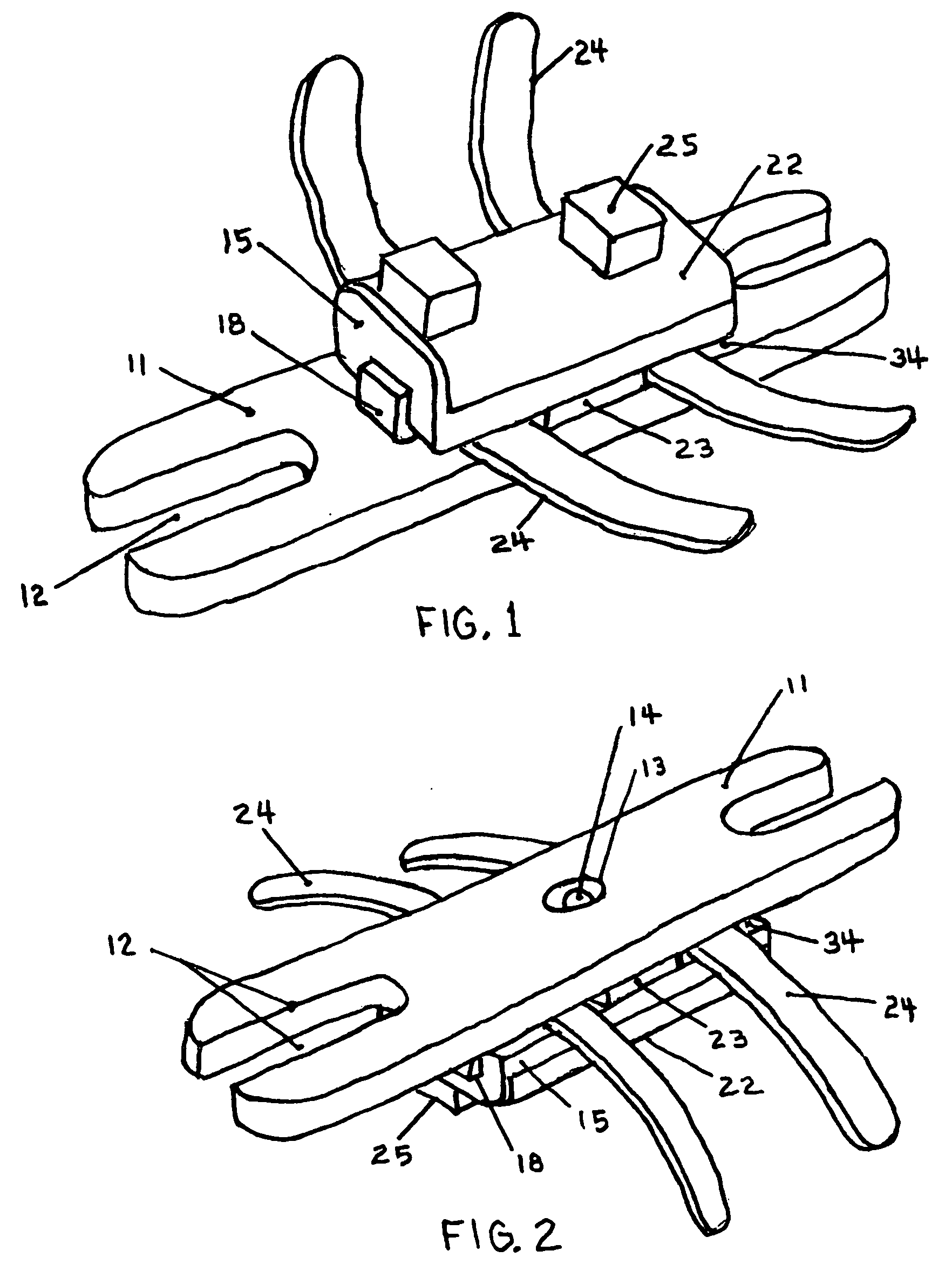
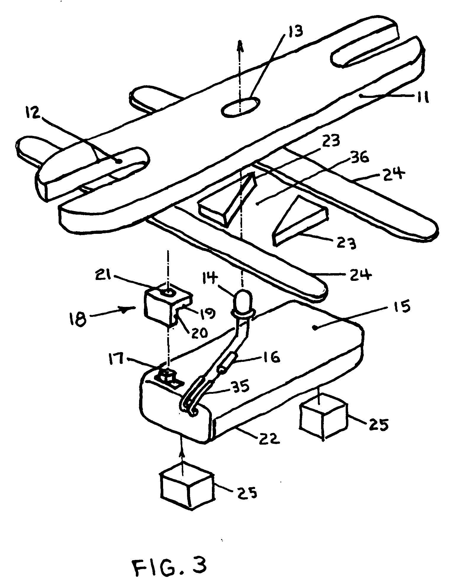
[0074]FIG. 1 and FIG. 2 are perspective views of a first preferred embodiment of a universal croquet wicket light unit constructed in accordance with the claims of my invention. This presents an overview of how components are arranged on the mounting plate to form the unit. In particular, this shows how: battery power 15 is provided and switched on and off 18; how the light emitting diode 14 is positioned; how the retaining straps 24 and friction pads 25 are configured and positioned relative to one another and the overall unit; and, the relationship of these components to the mounting plate 11. The circuit providing power to the light emitting diode consists of the diode, the batteries, the switch, and a current limiting resistor. How these components are typically positioned is shown as an exploded perspective view in FIG. 3.

[0075] A battery holder 15, comprising of an internally integrated switch, a switch knob 17 that presents itself externally to the battery ...

second embodiment

A SECOND EMBODIMENT

[0079] A second preferred embodiment of the wicket light unit is different from the first embodiment, only due to a slight difference in the battery holder unit incorporated in the embodiments. This difference is characterized by the location for the switch knob on the battery holder. In the first embodiment, the switch knob 17 was located on the side opposite to the battery cover 22. It is possible to utilize a battery holder with the switch knob located either on the same side as, or on a side adjacent to, the battery cover. This eliminates the slide actuator 18 mechanism described in the first embodiment since a user would have direct access for actuating a switch knob so located. Battery holders such as described in this second embodiment are usually less compact, and more expensive to manufacture; this is why the first and third embodiments do not incorporate this style of battery holder, even though an additional switch actuation mechanism is required. All o...

third embodiment

A THIRD EMBODIMENT

[0080]FIG. 9 illustrates aspects of a third preferred embodiment of the wicket light unit. This embodiment is different from the first embodiment, only in that the separation space between the battery holder and the mounting plate, needed for mounting components, is provided in a different fashion than in the first embodiment. In this third embodiment, separation space and component channels are created as recesses in the mounting plate. In the first embodiment, standoff spacers are employed exclusively to create the separation space and component channels.

[0081] Whereas the invention has been shown and described in connection with preferred embodiments thereof, it will be understood that many modifications, substitutions and additions may be made that are within the intended broad scope of the claims. There has therefore been shown and described three such embodiments based on the claims in my patent, and which accomplishes all the stated objectives pertaining to...


PUM


Abstract

A croquet wicket lighting unit to provide illumination in the vicinity of a wicket to facilitate playing the game of croquet under conditions of low illumination. Components are attached to a mounting plate 11 that straddles the wicket. The mounting plate universally and firmly attaches to any size or style of wicket by means of retaining straps 24 and friction pads 25 in combination with universal engaging slots 12. The illumination element directs an intense beam of focused light through a hole 13 in the mounting plate and onto the playing surface immediately under the wicket to clearly reveal the passage of a ball through the wicket. The illumination scheme also casts a larger area of more diffuse light on the playing surface immediately adjacent to the focus spot to reveal croquet balls resting therein and facilitate play around the wicket. Batteries contained in a battery holder 15, with an on-off electric switch 18, provide power through a resistor 16 to a light emitting diode 14 as the source of illumination. Light emitting diodes are selected with predetermined brightness and cone of focus to provide both intense and efficient lighting. Component selection, and design are such as to provide impact tolerance against the environment of mallet and ball strikes inherent in croquet play.

Description

CROSS-REFERENCE TO RELATED INVENTIONS [0001] Not Applicable STATEMENT REGARDING FEDERALLY SPONSORED RESEARCH OR DEVELOPMENT [0002] Not Applicable REFERENCE TO SEQUENCE LISTING, A TABLE, OR A COMPUTER PROGRAM LISTING COMPACT DISK APPENDIX [0003] Not Applicable BACKGROUND OF THE INVENTION [0004] This invention pertains to the game of croquet, a game played out of doors on a course usually laid out on grass lawns. The equipment needed to play croquet, called a “croquet set”, consists of balls, striking mallets, wickets, and stakes. Wickets are in the general shape of an inverted “U”, the two legs of which are called stanchions. The two stanchions are impaled in the ground forming an arch through which a ball may pass. Stakes delineate various points of play within the course. The balls, precisely driven with mallets, are aimed at and must pass through wickets, with the game's objective being to traverse the course using fewer mallet strikes than opponents. The game of croquet tradition...

Claims


Application Information

Patent Timeline
Patent Type & Authority Applications(United States)
IPC IPC(8): A63B59/10A63B63/00A63B67/00
CPCA63B59/10A63B2207/02A63B63/00A63B2102/36A63B59/60A63B2225/74
Inventor LANG, DAVID DELL
Owner LANG DAVID DELL
Features
  • R&D
  • Intellectual Property
  • Life Sciences
  • Materials
  • Tech Scout
  • Unparalleled Data Quality
  • Higher Quality Content
  • 60% Fewer Hallucinations
Learn More