Supercharge Your Innovation With Domain-Expert AI Agents!

Heat dissipation device and projector

a heat dissipation device and projector technology, applied in semiconductor devices, lighting and heating apparatus, instruments, etc., can solve the problems of insufficient heat dissipation efficiency of light-emitting diodes, inability to effectively and rapidly transmit heat energy to the fins, and high operating temperature of phosphor layers, etc., to achieve high heat dissipation efficiency and long service life

Inactive Publication Date: 2020-05-07
YOUNG OPTICS
View PDF1 Cites 0 Cited by
  • Summary
  • Abstract
  • Description
  • Claims
  • Application Information

AI Technical Summary

Benefits of technology

The invention is a heat dissipation device and a projector that use thermoelectric cooling technology to efficiently dissipate heat and have a long service life. This improves the reliability and performance of the heat dissipation device and the projector.

Problems solved by technology

The existing green light-emitting diode (LED) has insufficient light-emitting efficiency; hence, the green beam is mostly generated by irradiating phosphor by a blue beam, a UV beam, or another light source with short-wavelength as an excitation light, so that the phosphor is excited to form the green beam.
However, due to the thermal resistance of the substrate, heat energy cannot be transmitted to the fin effectively and rapidly on a large scale; thereby, the operating temperature of the phosphor layer is still high.
Nevertheless, motor driving parts is utilized for rotating the phosphor wheel and the color wheel may deteriorate the reliability of the system, so that the system life time cannot be effectively extended.

Method used


Image

  • Heat dissipation device and projector
  • Heat dissipation device and projector
  • Heat dissipation device and projector

Examples


Embodiment Construction

[0016]Reference will now be made in detail to the present embodiments of the invention, examples of which are illustrated in the accompanying drawings. Wherever possible, the same reference numbers are used in the drawings and the description to refer to the same or like parts.

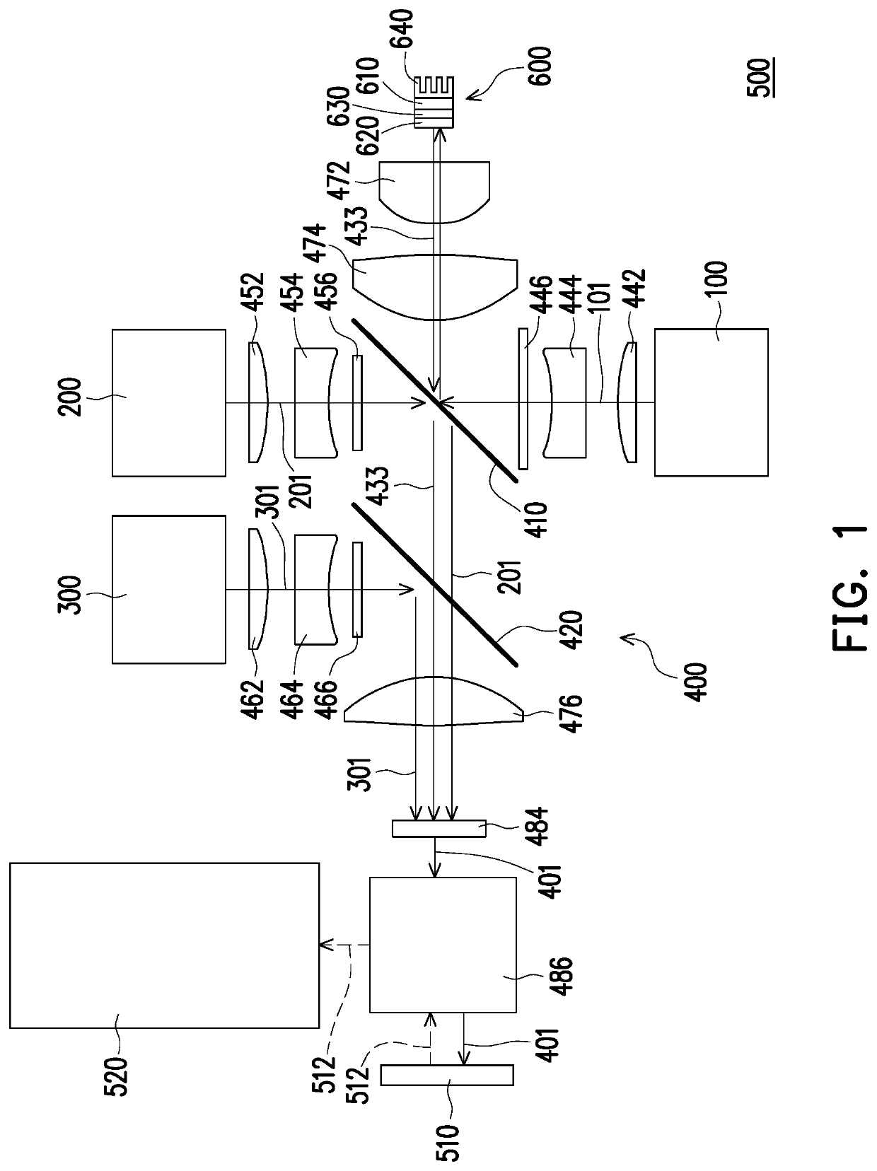
[0017]FIG. 1 is a schematic view illustrating a light path of a projector according to an embodiment of the invention. For instance, in the heat dissipation structure of a phosphor layer in a projector provided in an embodiment, a thermoelectric cooling chip is applied to assist in heat dissipation of the phosphor layer, whereby good heat dissipation effects can be achieved, the operating temperature of the phosphor layer can be reduced, and the service life of the phosphor layer can be extended. Besides, driving parts including a rotatable phosphor wheel can be selectively omitted, and therefore the reliability and the service life of the projector can be improved. The design of the projector provided herein ...


PUM

PropertyMeasurementUnit
thicknessaaaaaaaaaa
power consumption rateaaaaaaaaaa
poweraaaaaaaaaa

Abstract

A heat dissipation device including two insulation layers, two metal layers, a semiconductor layer, and a phosphor layer is provided. The semiconductor layer is disposed between the two metal layers, and the whole of the semiconductor and the two metal layers is disposed between the two insulation layers. The phosphor layer is disposed on one of the insulation layers. A projector is also provided.

Description

CROSS-REFERENCE TO RELATED APPLICATION[0001]This application claims the priority benefit of Taiwan application serial no. 107139173, filed on Nov. 5, 2018. The entirety of the above-mentioned patent application is hereby incorporated by reference herein and made a part of this specification.BACKGROUND OF THE INVENTIONField of the Invention[0002]The invention relates to an optical device. More particularly, the invention relates to a heat dissipation device and a projector.Description of Related Art[0003]The existing green light-emitting diode (LED) has insufficient light-emitting efficiency; hence, the green beam is mostly generated by irradiating phosphor by a blue beam, a UV beam, or another light source with short-wavelength as an excitation light, so that the phosphor is excited to form the green beam. Generally, the conversion efficiency of the phosphor is proportional to the energy density of the excitation light received by the phosphor, and the higher the energy density of t...

Claims


Application Information

Patent Timeline
Patent Type & Authority Applications(United States)
IPC IPC(8): G03B21/16H01L35/32H01L33/64F21K9/64H10N10/17
CPCF21K9/64H01L33/645H01L35/32G03B21/16G03B21/204H01L33/642H10N10/17
Inventor HUANG, JIA-BIN
Owner YOUNG OPTICS
Features
  • R&D
  • Intellectual Property
  • Life Sciences
  • Materials
  • Tech Scout
  • Unparalleled Data Quality
  • Higher Quality Content
  • 60% Fewer Hallucinations
Learn More