Devices for physiological fluid sampling and methds of using the same

a technology of physiological fluid and device, applied in the field of physiological fluid sampling, can solve the problems of inability to properly control the glucose level, pain associated with sample collection, and inability to accurately measure the level of glucose,

Inactive Publication Date: 2005-05-26
LIFESCAN IP HLDG LLC
View PDF39 Cites 86 Cited by
  • Summary
  • Abstract
  • Description
  • Claims
  • Application Information

AI Technical Summary

Benefits of technology

[0010] Methods and devices are provided for determining a suitable site for sampling physiological fluid. In the subject methods, a potentially suitable physiological sampling site is selected, the fluid flow of the site is characterized and the site is then determined to be suitable based on the whether the site has high or low flow. Suitability may also be determined based on the type of sample obtainable from the site, where the order of the above-described steps may be altered. The subject devices include at least one site flow characteri

Problems solved by technology

First and foremost, such processes or techniques are associated with a significant amount of pain.
The pain associated with sample collection may have serious adverse consequences for those who require analyte characterizations to be performed, e.g., analyte detection and/or concentration determinations.
For instance, patients who require frequent analyte concentration determinations may not adhere to their requisite testing protocols due to this associated pain and it is not uncommon for patients who require frequent monitoring of an analyte to simply avoid monitoring the analyte of interest because of the pain involved in sample collection.
With diabetics, for example, the failure to measure their glucose level on a prescribed basis results in a lack of information necessary to properly control the level of glucose.
Uncontrolled glucose levels can be very dangerous and even life threatening.
However, collecting a physiological fluid sample from the

Method used


Image

  • Devices for physiological fluid sampling and methds of using the same
  • Devices for physiological fluid sampling and methds of using the same
  • Devices for physiological fluid sampling and methds of using the same

Examples


Embodiment Construction

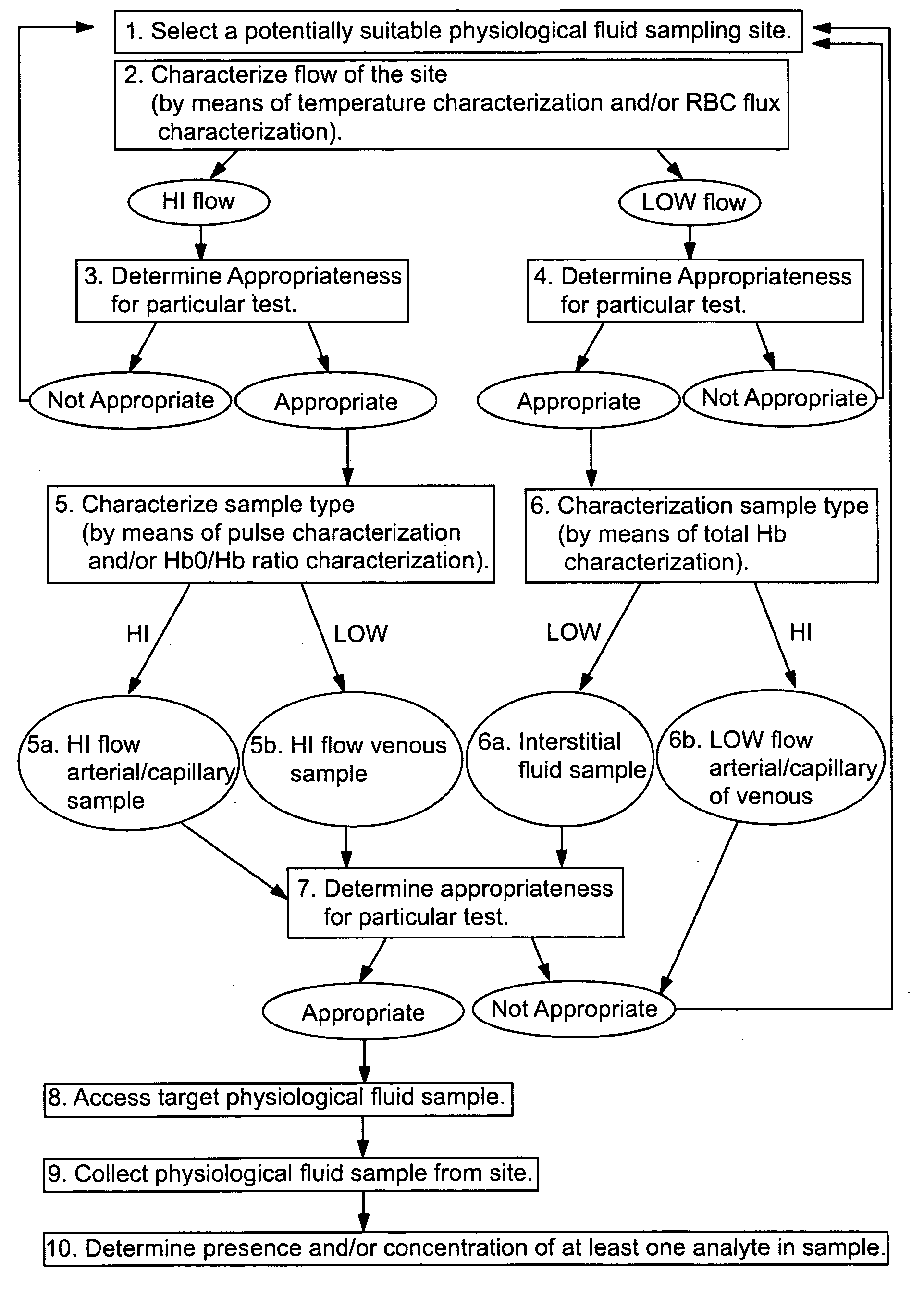
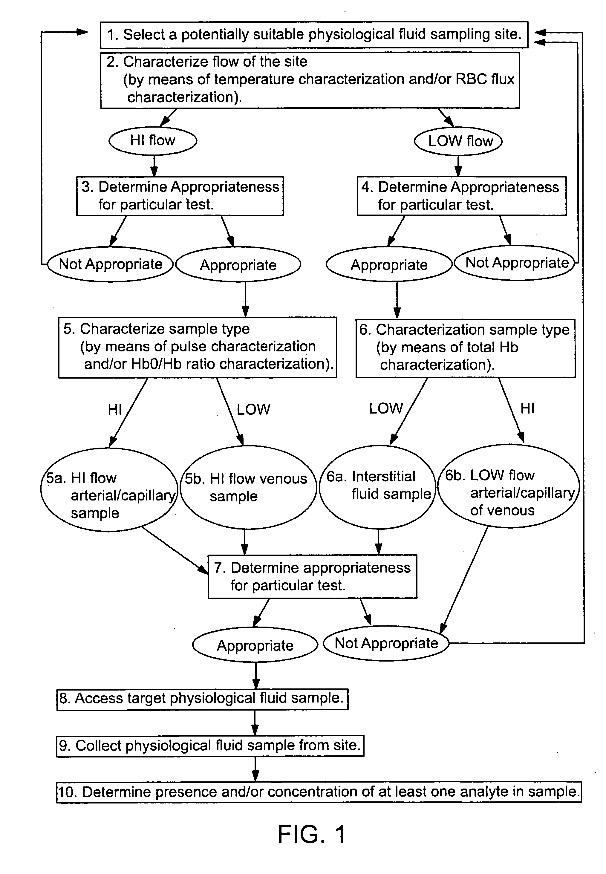
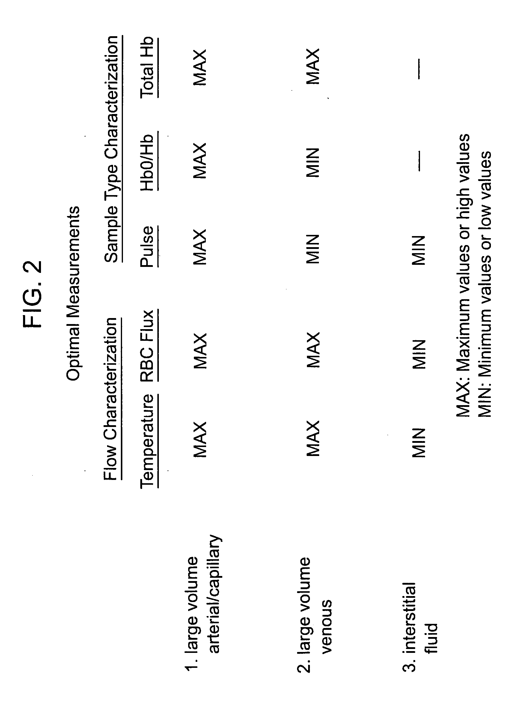
[0016] Methods and devices are provided for determining a suitable site for sampling physiological fluid. In the subject methods, a potentially suitable physiological sampling site is selected, the fluid flow of the site is characterized and the site is then determined to be suitable based on the whether the site has high or low flow. Suitability may also be determined based on the type of sample obtainable from the site, where the order of the above-described steps may be altered. The subject devices include at least one site flow characterization element for determining the flow characteristics of a potential physiological sampling site and / or at least one sample type characterization element for determining whether the vasculature is arterial, venous or neither, i.e., an interstitial fluid sampling site. The subject methods and devices are particularly suited for use in the detection of physiological sampling sites in the fingers, arms, legs, earlobes, heels, feet, nose and toes....


PUM


Abstract

Methods and devices are provided for determining a suitable site for sampling physiological fluid. In the subject methods, a potentially suitable physiological sampling site is selected, the fluid flow of the site is characterized and the site is then determined to be suitable based on the whether the site has high or low flow. Suitability may also be determined based on the type of sample obtainable from the site, where the order of the above-described steps may be altered. The subject devices include at least one site flow characterization element for determining the flow characteristics of a potential physiological sampling site and/or at least one sample type characterization element for determining whether the vasculature is arterial, venous or neither, i.e., an interstitial fluid sampling site. The subject methods and devices are particularly suited for use in the detection of physiological sampling sites in the fingers, arms, legs, earlobes, heels, feet, nose and toes. Also provided are kits that include the subject devices for use in practicing the subject methods.

Description

FIELD OF THE INVENTION [0001] The field of this invention is physiological fluid sampling and more particularly devices and methods of use thereof for non-invasively determining suitable physiological fluid sampling sites. BACKGROUND OF THE INVENTION [0002] Analyte concentration characterization in physiological samples is of ever increasing importance to today's society. Such assays find use in a variety of application settings, including clinical laboratory testing, home testing, etc., where the results of such testing play a prominent role in the diagnosis and management of a variety of disease conditions. Analytes of interest include glucose for diabetes management, cholesterol for monitoring cardiovascular conditions, and the like. In response to this growing importance of analyte concentration characterization, a variety of analyte concentration characterization protocols and devices for both clinical and home testing have been developed. [0003] To determine the concentration ...

Claims


Application Information

Patent Timeline
IPC IPC(8): A61B5/00A61B5/026G01N33/48A61B5/103A61B5/145A61B5/1473A61B5/15A61B5/157A61B10/00A61B17/00G01N33/487
CPCA61B5/1411A61B5/14532A61B5/489A61B10/0045A61B5/14551A61B2017/00057A61B5/14546A61B5/1455A61B2010/008A61B5/150022A61B5/15003A61B5/150305A61B5/150358A61B5/150412A61B5/150748A61B5/150954A61B5/15107A61B5/15117A61B5/157A61B5/0059A61B5/0261A61B5/14514A61B5/150076A61B5/150083A61B5/150503A61B5/15109A61B5/15113A61B5/1519A61B5/441G01N33/49G01N33/80G01N33/487
Inventor MATZINGER, DAVIDQURAISHI, KHALID R.
Owner LIFESCAN IP HLDG LLC
Why Eureka
Try Eureka