Surgical implant

a surgical and implant technology, applied in the field of medical devices, can solve the problems of ineffective implants, requiring follow-up or additional medical procedures, and the size of the presently available implants,

Inactive Publication Date: 2005-05-26
WILSONCOOK MEDICAL
View PDF13 Cites 35 Cited by
  • Summary
  • Abstract
  • Description
  • Claims
  • Application Information

AI Technical Summary

Benefits of technology

[0009] Accordingly, it is an object of the present invention to provide a medical device having features that resolve or improve upon one or more of the above-described drawbacks.

Problems solved by technology

However, presently available procedures for inserting an implant have several significant drawbacks, including implant migration.
In more serious cases, implant migration renders the implant entirely ineffective, thus requiring follow-up or additional medical procedures.
Another drawback is the size of presently available implants.
Often times a single implant is simply too small to achieve the desired bulk in the target area.
Delivering multiple implants, however, can require that a physician reinsert the delivery tool into a target tissue for each implant, thus increasing the time required for the procedure and causing unnecessary trauma.
First, creating a pouch for the implant typically causes excessive trauma to the surrounding tissues, especially if a blunt tool is used to create the pouch.
Another drawback is that insertion of an implant into the target tissue can be difficult because the implant can catch or snag on the edges of the mucosal incision.
Moreover, implants can be difficult to deliver into a target tissue along a desired trajectory and in a desired spatial orientation.

Method used


Image

  • Surgical implant
  • Surgical implant
  • Surgical implant

Examples


first embodiment

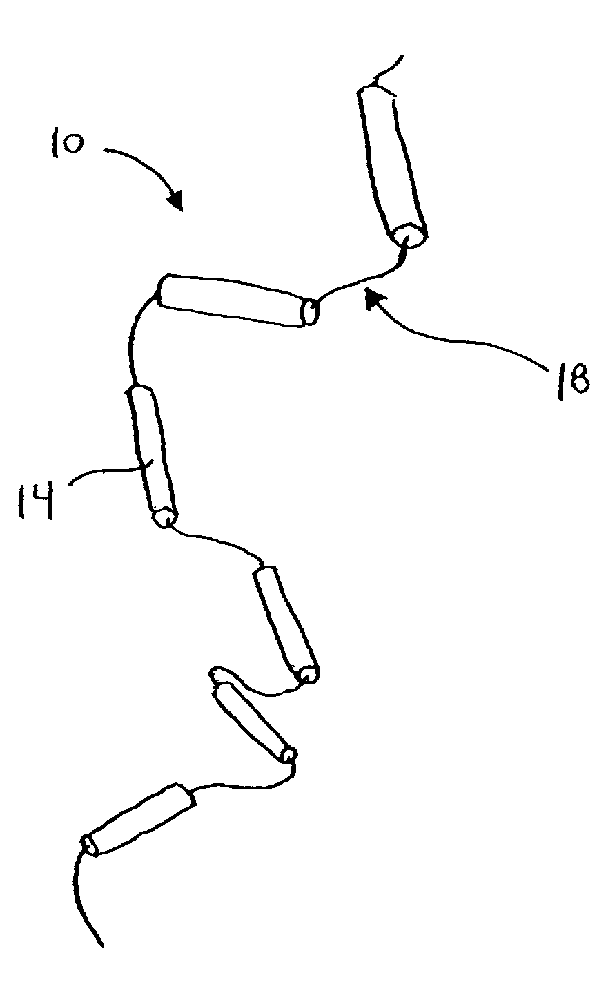
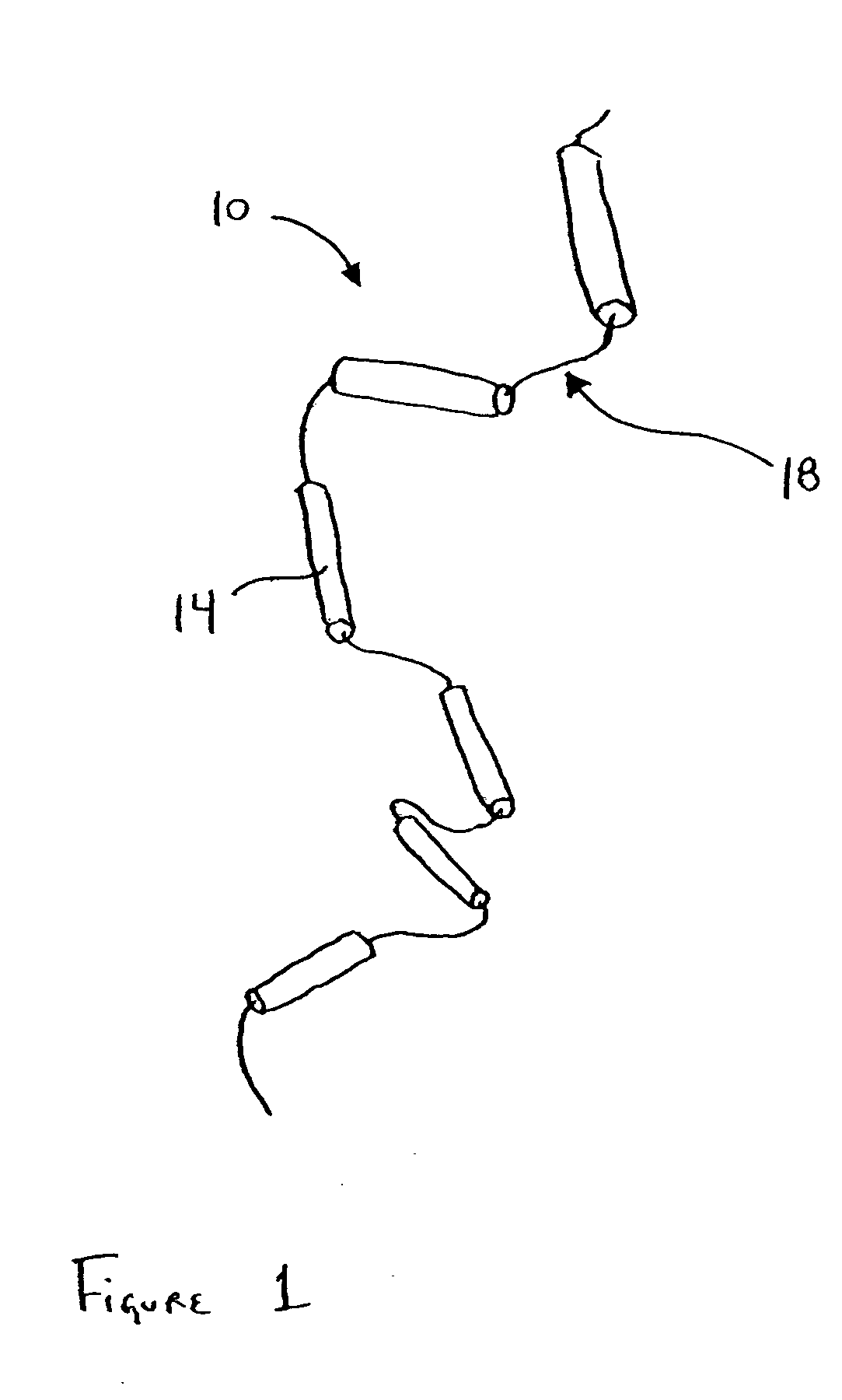
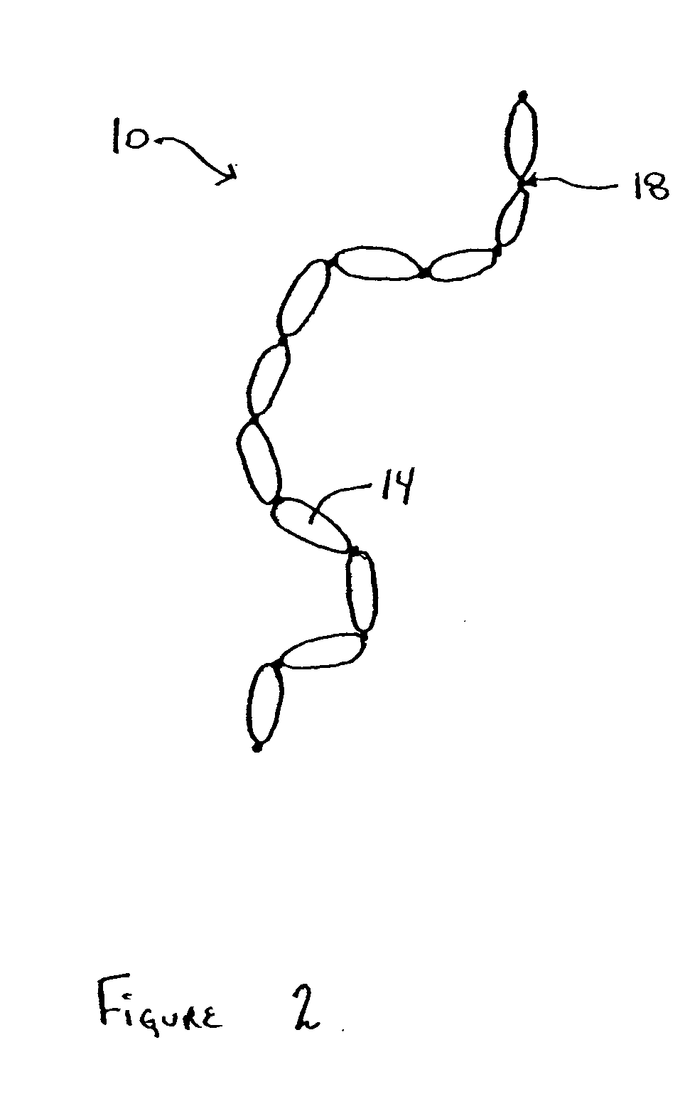
[0030] Referring to the drawings, FIG. 1 illustrates the present invention, and particularly, linked implant 10. As illustrated in FIGS. 1-4, linked implant 10 normally comprises two or more implant bodies 14 attached to a string 18. In general, linked implant 10 is delivered to a location adjacent the target tissue (e.g., the esophageal lumen, superior to the LES). Linked implant 10 is then introduced into the target tissue, thereby bulking the surrounding tissue.

[0031] Implant body 14 can be formed of a variety of desirable, biocompatible implant materials suitable for bulking and supporting a target tissue. In a preferred embodiment of the present invention, the implant body is formed of a bio-remodelable, extra-cellular matrix. One suitable form of extra-cellular matrix is harvested from porcine or bovine small intestine submucosa (hereinafter “SIS”). SIS is a preferred material because it has special bio-remodeling characteristics. Because of these characteristics, SIS has been...

second embodiment

[0043] Referring to the drawings, FIGS. 15 and 16 illustrate the present invention, and particularly, tipped implant 110. As best seen in FIG. 15, tipped implant 110 generally comprises implant body 126 (often having a rough or non-uniform edge), and a smooth implant tip 114 having a penetrating portion and an expanding portion. As illustrated in FIG. 17, tip 114 also includes a proximal end having shank 132 with threads 134. As discussed in greater detail below, shank 132 secures implant body 126 to tip 114.

[0044] In general, tipped implant 110 is delivered to a location adjacent the target tissue (e.g., the esophageal lumen, superior to the LES) through the working channel of an endoscope. Tip 114 is then introduced into the target tissue such that the penetrating portion of the tip punctures the target tissue. As the tip is advanced into the target tissue, the expansion portion of the tip widens the puncture created by the penetrating portion, thus forming a cavity sized to recei...


PUM


Abstract

An implant is disclosed including a bio-compatible implant body that can be provided with a tip, or interconnected by one or more filaments. The implant body can be formed of a variety of biocompatible materials, including bio-remodelable materials such as small intestine submucosa. Methods are disclosed for assembly of the implant. Additionally, a method is disclosed for delivering the implant to a desired location in a patient.

Description

RELATED APPLICATIONS [0001] This claims the benefit of U.S. Provisional Application Ser. No. 60 / 494,613, entitled “Tipped Implant,” filed on Aug. 11, 2003, and U.S. Provisional Application Ser. No. 60 / 558,163, entitled “Surgical Graft,” filed on Mar. 30, 2004.TECHNICAL FIELD [0002] This invention relates to medical devices, and more particularly, to surgical implants. BACKGROUND [0003] Many surgical or endoscopic applications require the insertion of an implant into an incision in a patient's soft tissue. For example, such implants can be used to add bulk to a target tissue, thereby reinforcing the target tissue area. These procedures are often referred to as “bulking” procedures, and are frequently used in treating urological diseases, including urinary incontinence and vesicourethral reflux disease. “Bulking” procedures are also often used to treat Gastroesophageal Reflux Disease (hereinafter “GERD”). GERD is a form of dyspepsia that afflicts approximately 40% of adults in the Uni...

Claims


Application Information

Patent Timeline
Patent Type & Authority Applications(United States)
IPC IPC(8): A61B17/00A61B17/06A61B17/12A61B17/34A61F2/00A61F2/02
CPCA61B17/06166A61B17/12022A61B17/12099A61B17/12104A61B17/12131A61B17/12163A61M37/0069A61B2017/00004A61B2017/00526A61B2017/1205A61F2/0036A61F5/0069A61B17/3468
Inventor KENNEDY, KENNETH C. IICHIN, LIKANG
Owner WILSONCOOK MEDICAL
Why Eureka
Try Eureka