Rapid-exchange delivery systems for self-expanding stents

a technology of stents and stents, applied in the field of stent delivery systems, can solve the problems of reducing the overall flexibility of the delivery system, the problem of rotational alignment between the sheaths, and the addition of retractable sheaths, so as to reduce the profile of the stent delivery system, the effect of reducing the wall thickness

Inactive Publication Date: 2005-05-26
ABBOTT CARDIOVASCULAR
View PDF20 Cites 148 Cited by
  • Summary
  • Abstract
  • Description
  • Claims
  • Application Information

AI Technical Summary

Benefits of technology

[0011] In one particular aspect of the present invention, the inner member of the composite rapid-exchange catheter assembly includes a proximal portion made from a hypotube which minimizes the chance of compression or tensile forces acting on the catheter assembly. The hypotube also provides a channel for flushing the system with a fluid, such as saline, prior to usage. In this manner, the inner member provides a conduit for helping evacuate air bubbles from the catheter assembly prior to usage. In one particular embodiment of the invention, the proximal portion of the inner member can be made from polymeric coated coil tubing which is utilized to help prevent compression of the inner member without decreasing the flexibility of the rapid-exchange delivery system. Such a tubing also could be used in an over-the-wire stent delivery system. In yet another aspect of the invention, the polymeric coated coil tubing could be utilized as the guide wire receiving member for a rapid-exchange version of the self-expanding stent system. The use of this polymeric coated coil tubing should not reduce the flexibility or trackability of the catheter during usage, but should prevent compression or kinking when being deployed.
[0013] In another aspect of the present invention, the distal portion of the outer member which forms the restraining sheath portion of the self-expanding stent delivery system can be made from a Nylon-coated polyimide material that provides high-strength tubing with a low-wall thickness. Such a material can resist an equal amount of hoop stress at a much lower wall thickness than with a Nylon material alone. In one component, a Nylon material is bonded to the outside of a polyimide tubing. The inner surface of the polyimide tubing remains resistant to stent-strut indentation caused by the outward radial force exerted by the collapsed self-expanding stent. The Nylon material bonded to the outside of the sheath portion provides the necessary tubing strength to restrain the stent in a collapsed delivery position, but with a lower wall thickness. As a result, the profile of the stent delivery system can be reduced at its distal region by utilizing such a composite material.

Problems solved by technology

One of the problems associated with the prior art catheter-delivery systems which use a retractable outer sheath is that the addition of a retractable sheath tends to reduce the overall flexibility of the delivery system.
However, there is still a need to maintain a low-profile in the distal region of the catheter delivery system in order to track the sometimes tortuous anatomy to deliver the stent to the target area.
Another problem that exists in the case of the rapid-exchange delivery system is that the addition of a retractable sheath to surround the catheter introduces a problem of rotational alignment between the sheath and the catheter.
If, during the foregoing process, the sheath rotates relative to the catheter, the surgeon may have difficulty in aligning the opening with the guide wire tip, so as to get the guide wire tip to protrude from the opening.
This complication can be a major problem for the surgeon to resolve under the pressure of surgery.

Method used


Image

  • Rapid-exchange delivery systems for self-expanding stents
  • Rapid-exchange delivery systems for self-expanding stents
  • Rapid-exchange delivery systems for self-expanding stents

Examples


Embodiment Construction

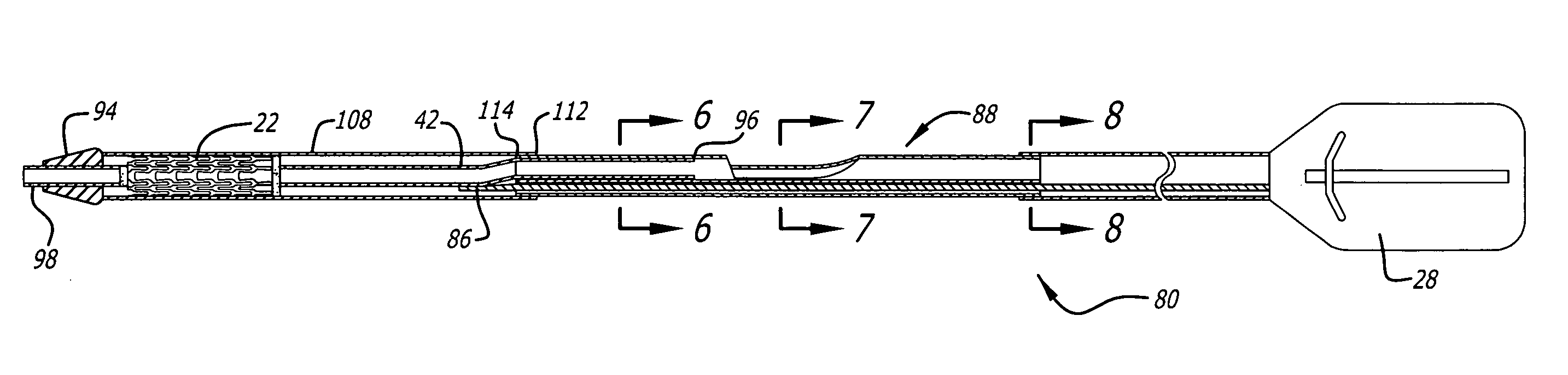
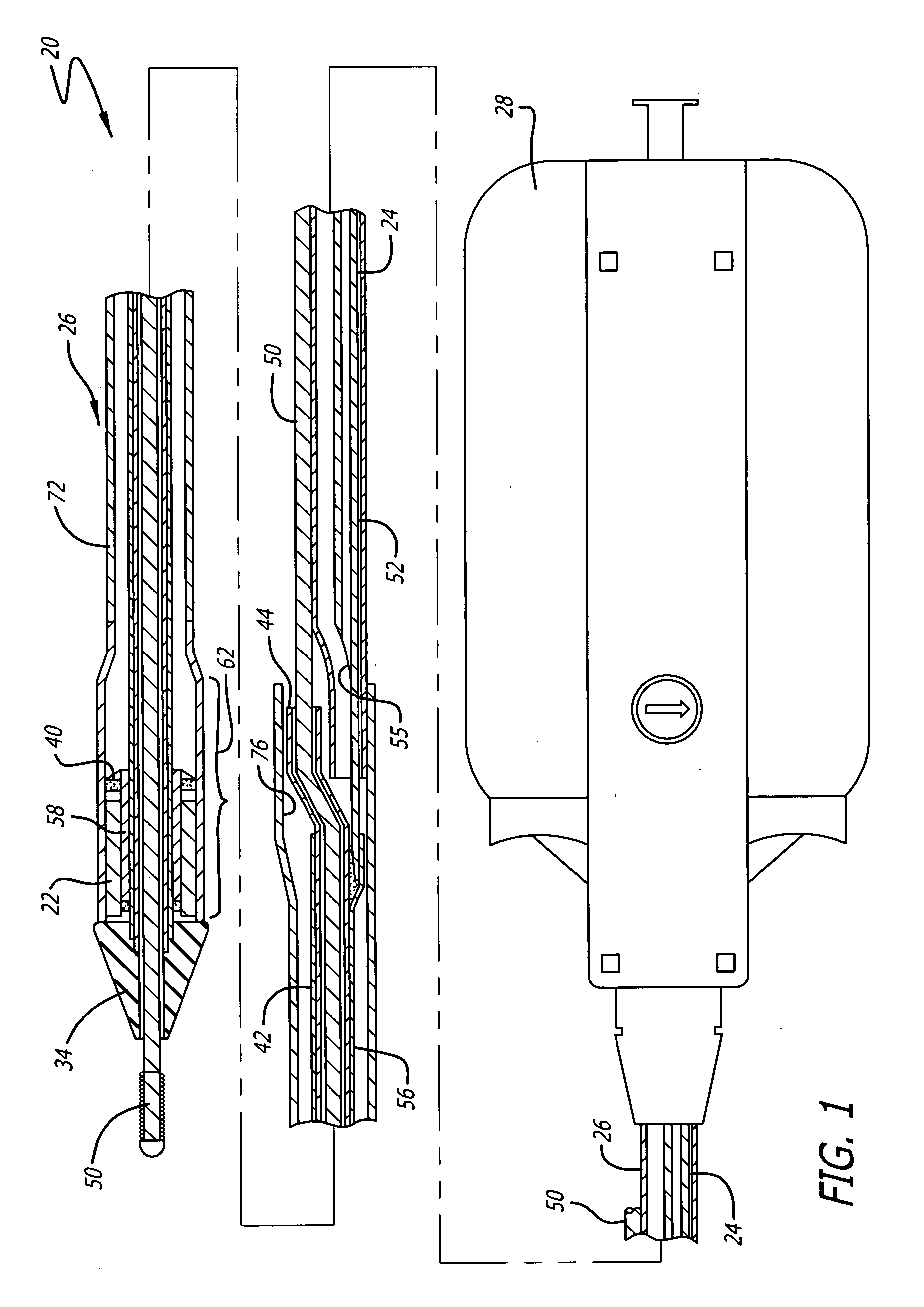
[0038] The present invention relates to rapid-exchange delivery catheter systems in which a stent is delivered intraluminally into a human patient's body lumen, such as a coronary artery, carotid artery, renal artery, peripheral artery and veins, and the like, and implanted therein.

[0039] There are numerous prior art stent delivery systems which may be used in conjunction with the present invention. The stent delivery systems suitable for use with the present invention are “rapid-exchange” delivery systems which have an outer sheath adapted to slide over an inner catheter so as to cover a stent. The invention described in detail herein is described in the context of an elastically self-expanding stent delivery system. However, the invention is not limited to such use, and may equally be used with a delivery system for a balloon expanded stent or heat-expanded stent.

[0040] In one embodiment of the invention, as exemplified in FIG. 1, a rapid-exchange catheter assembly 20 is provide...


PUM

PropertyMeasurementUnit
movementaaaaaaaaaa
flexibleaaaaaaaaaa
plastic deformationaaaaaaaaaa

Abstract

A catheter assembly is provided having an inner member and an outer member extending along a longitudinal axis, the inner member and the outer member having a coaxial configuration and dimensioned for relative axial movement. The outer member may include an anti rotation member adapted to engage with a longitudinal slot formed on the inner member so as to maintain rotational alignment between inner member and outer member. The inner member can be made with a proximal portion made from a tubing such as hypotubing or a coil tubing. The inner member also may be made with a proximal portion made with a support mandrel. A coil tubing can be utilized to form the guide wire receiving member which is attached to the inner member.

Description

BACKGROUND OF THE INVENTION [0001] The invention relates to stent delivery systems, which are used to implant a stent into a patient's body lumen to maintain the patency thereof. The stent delivery system is useful in the treatment and repair of body lumens, including coronary arteries, renal arteries, carotid arteries, and other body lumens. [0002] Stents are generally cylindrically-shaped devices which function to hold open and sometimes expand a segment of a blood vessel or other body lumen. They are particularly suitable for use to support and hold back a dissected arterial lining which can occlude the fluid passageway therethrough. Stents also are useful in maintaining the patency of a body lumen, such as a coronary artery, after a percutaneous transluminal coronary angioplasty (PTCA) procedure or an atherectomy procedure to open a stenosed area of the artery. [0003] Typically, a stent is delivered intraluminally through a percutaneous incision through the femoral or renal arte...

Claims


Application Information

Patent Timeline
Patent Type & Authority Applications(United States)
IPC IPC(8): A61F2/84A61L29/00A61M25/00
CPCA61F2/95A61M2025/0183A61F2/966
Inventor GEISER, TIMOTHY A.PETERSON, CHARLES R.DENISON, ANDYKLOCKE, STEPHANIEPATEL, SAMIRLUBAS, JOANNALUMAUIG, JOANNELIND, KATHYFITZGERALD, KEIF
Owner ABBOTT CARDIOVASCULAR
Why Eureka
Try Eureka